Position pointer, variable capacitor and inputting apparatus

a technology of variable capacitor and pointer, which is applied in the direction of instruments, diagnostic recording/measuring, force/torque/work measurement apparatus, etc., can solve the problems of dielectric member 201/b> degrading to deteriorate the durability of variable capacitor, and achieves the effect of improving durability, reducing the number of fabrication steps, and superior durability

Active Publication Date: 2014-12-16
WACOM CO LTD
View PDF31 Cites 45 Cited by
  • Summary
  • Abstract
  • Description
  • Claims
  • Application Information

AI Technical Summary

Benefits of technology

[0016]According to one aspect, the present invention provides a position pointer, a variable capacitor and an inputting apparatus by which an initial state can be restored with certainty, reduction in the number of fabrication steps can be achieved, and durability can be improved.
[0020]In the position pointer and the variable capacitor, the terminal member of the variable capacitor engages with the first face portion side of the dielectric member and plays a role of the first electrode. Accordingly, there is no necessity to separately form an electrode on the first face portion side of the dielectric member, and a step for the electrode formation can be omitted. Further, since there is no possibility of abrasion of the terminal member and the electrode on the first face portion of the dielectric member by contact therebetween, the durability of the position pointer and the variable capacitor can be improved.
[0022]Accordingly, a situation that the conductive member of the electrode section sticks to the second face portion of the dielectric member can be prevented, and consequently, the position pointer and the variable capacitor are superior in durability.
[0023]In summary, with the present invention, a position pointer, a variable capacitor and an inputting apparatus can be provided wherein the variable capacitor can restore its original state with certainty and which can be produced by a reduced number of fabrication steps and can achieve improvement in durability.

Problems solved by technology

Therefore, there is another drawback that the second electrode 203 or the dielectric member 201 is degraded to deteriorate the durability of the variable capacitor 200.

Method used


Image

  • Position pointer, variable capacitor and inputting apparatus
  • Position pointer, variable capacitor and inputting apparatus
  • Position pointer, variable capacitor and inputting apparatus

Examples


first embodiment

[0066]In the following, a position pointer, a variable capacitor and an inputting apparatus according to a first embodiment of the present invention are described with reference to FIGS. 1 to 25.

[Inputting Apparatus]

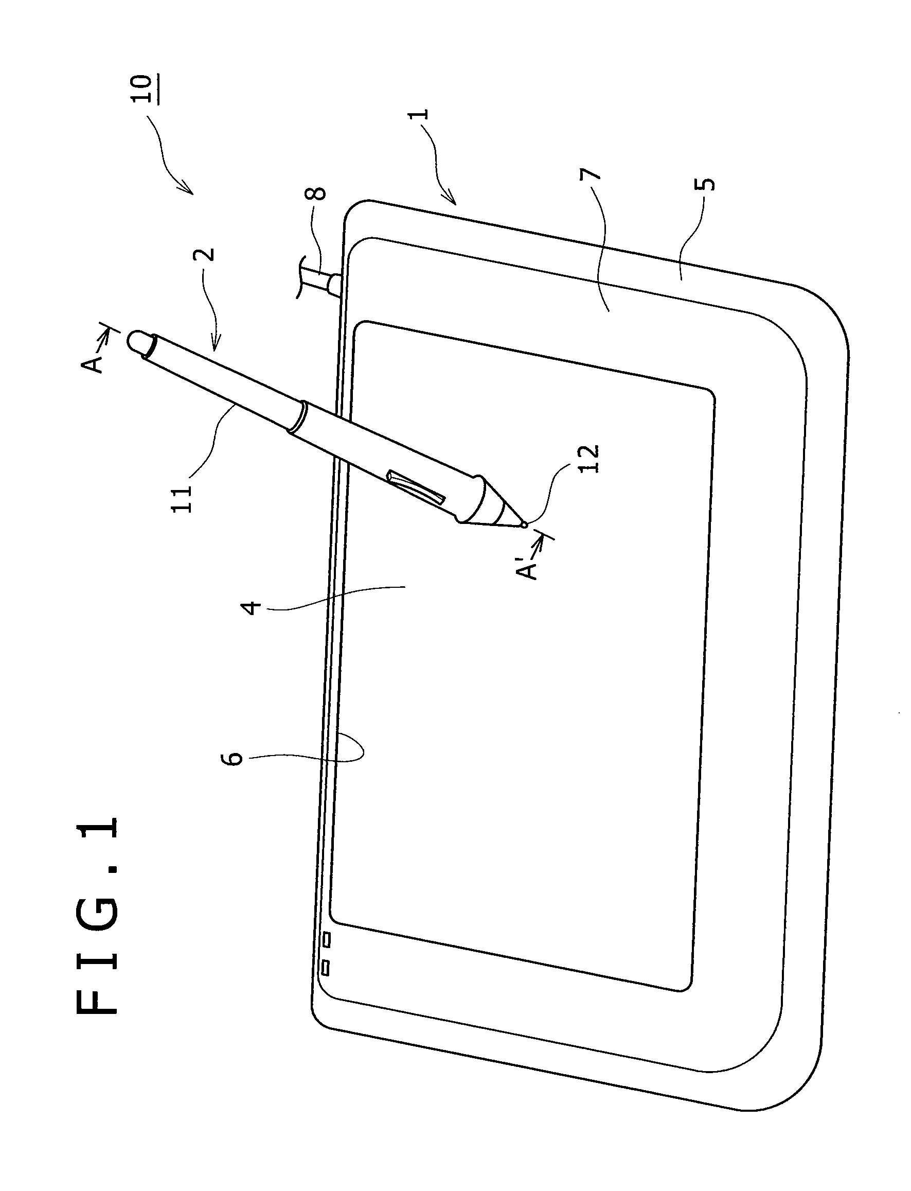
[0067]First, a general configuration of an inputting apparatus according to the first embodiment of the present invention is described with reference to FIG. 1. FIG. 1 is a perspective view showing the inputting apparatus according to the present invention.

[0068]The inputting apparatus 10 according to the first embodiment of the present invention includes a position detection apparatus 1, and a position pointer 2 for inputting information to the position detection apparatus 1.

[Position Detection Apparatus 1]

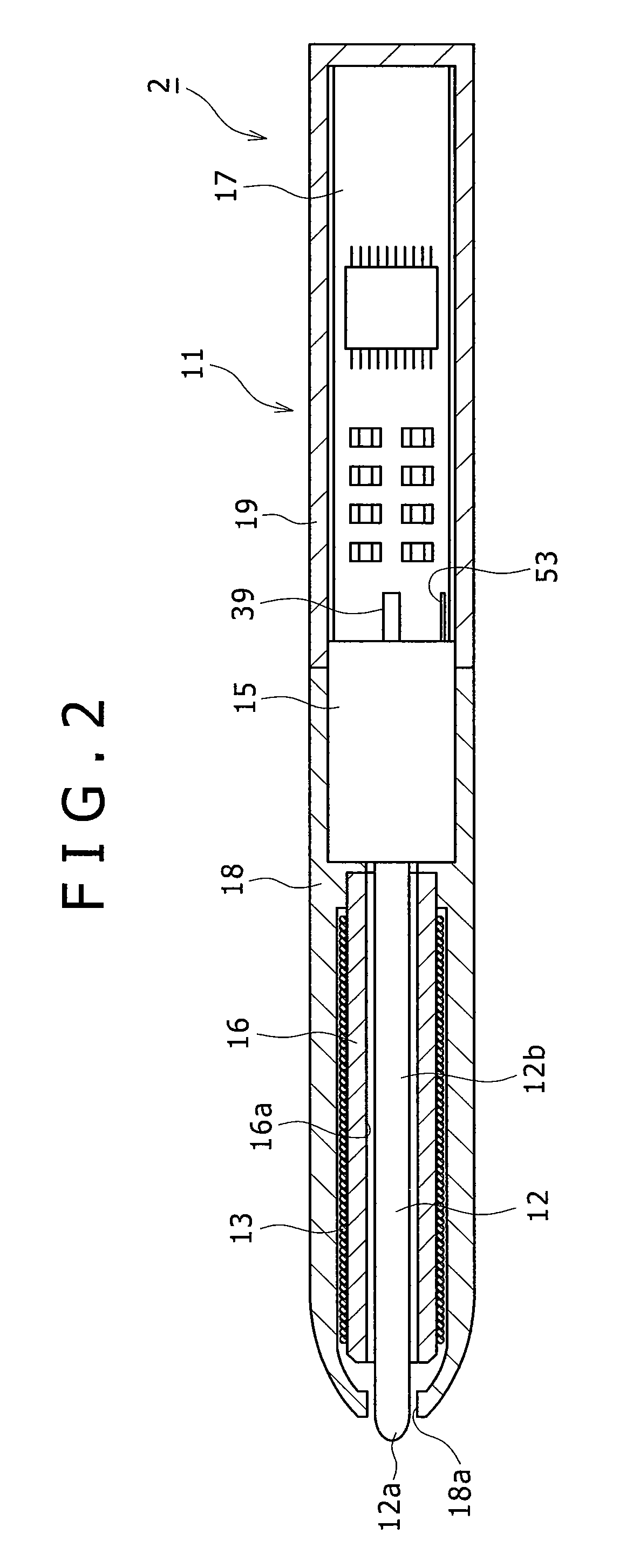
[0069]The position detection apparatus 1 is connected to an external apparatus such as a personal computer or a PDA (Personal Digital Assistant) (not shown) by a cable 8 so that it is used as an inputting apparatus for the external apparatus. Though not particularly s...

second embodiment

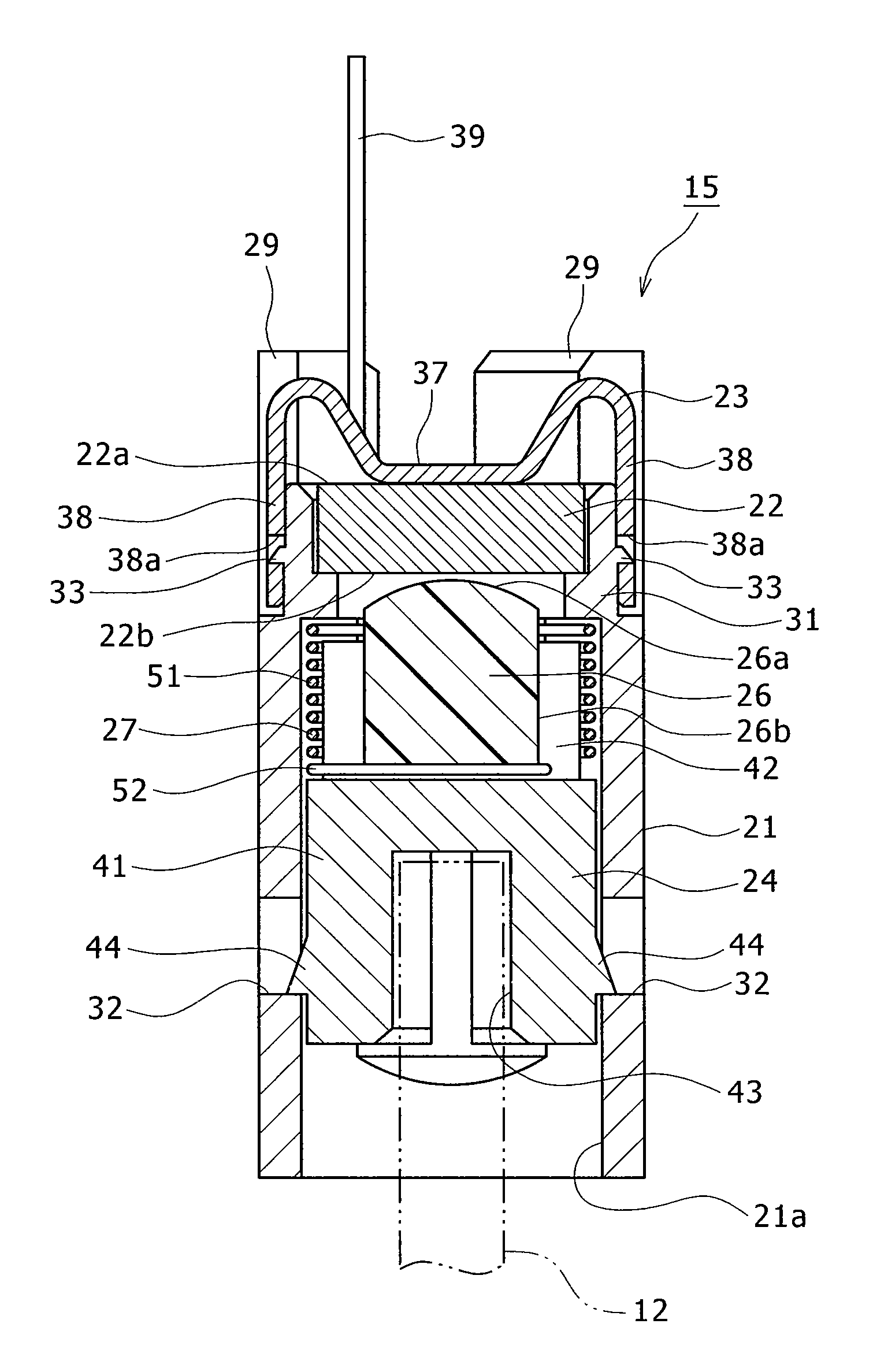
[0187]A variable capacitor for a position pointer according to a second embodiment of the present invention is similar in configuration to that according to the first embodiment described hereinabove except the configuration of the contacting portion between the flat portion 37 of the terminal member 23 and the first face portion 22a of the dielectric member 22. FIG. 26 shows a configuration of the variable capacitor 150 of the position pointer according to the second embodiment. It is to be noted that overlapping description of components of the variable capacitor 150 common to those of the variable capacitor 15 are omitted herein to avoid redundancy.

[0188]Referring to FIG. 26, in the present second embodiment, the flat portion 37 of the terminal member 23 provided on the first face portion 22a side of the dielectric member 22 does not directly contact the first face portion 22a of the dielectric member 22. Instead, a conductive elastic member 81 made of, for example, a conductive ...

third embodiment

[0192]A variable capacitor for a position pointer according to a third embodiment of the present invention is similar in configuration to those according to the first and second embodiments described hereinabove except the configuration of the contacting portion between the flat portion 37 of the terminal member 23 and the first face portion 22a of the dielectric member 22. Again, overlapping description of common components is omitted to avoid redundancy. Referring to FIG. 28, in the present third embodiment, a metal electrode 82 is formed over a region of the first face portion 22a of the dielectric member 22, which is equal to or greater in size than the area of the first face portion 22a of the dielectric member 22 which the flat portion 37 of the terminal member 23 contacts. The metal electrode 82 is formed, for example, by sintering silver paste to the first face portion 22a of the dielectric member 22.

[0193]Since the variable capacitor of the third embodiment is configured in...


PUM


Abstract

A position pointer is disclosed, including a housing, a substantially bar-like rod accommodated in the housing such that one end thereof projects to the outer side of the housing, and a variable capacitor having a capacitance value which varies in response to external force applied thereto through the rod. The variable capacitor includes a dielectric member having a first face portion and a second face portion opposite from the first face portion, a terminal member configured to engage with the first face portion of the dielectric member, an electrode section disposed in an opposing relationship to the second face portion of the dielectric member and including a conductive member having a contact area with the second face portion that varies in response to the external force, and an elastic member configured to bias the conductive member in a direction in which the conductive member is spaced away from the second face portion.

Description

CROSS-REFERENCE(S) TO RELATED APPLICATION[0001]The present application claims priority under 35 U.S.C. §119 from Japanese Patent Application JP 2010-051677 filed in the Japanese Patent Office on Mar. 9, 2010, the entire content of which is incorporated herein by reference.BACKGROUND OF THE INVENTION[0002]1. Field of the Invention[0003]This invention relates to a position pointer suitable for use for detection of writing pressure, a variable capacitor for detecting the writing pressure, and an inputting apparatus which includes the position pointer.[0004]2. Description of the Related Art[0005]In recent years, inputting apparatuses have been used as an inputting device for computing devices, such as personal computers and so forth. A typical inputting apparatus includes a position pointer formed, for example, like a pen, and a position detection apparatus having an input face which receives a pointing operation or inputting of characters, figures, and so forth thereto using the positi...

Claims


Application Information

Patent Timeline
Patent Type & Authority Patents(United States)
IPC IPC(8): G09G5/00G06F3/041G06F3/046G06F3/0354
CPCG06F3/0416G06F3/046G06F3/03545G06F3/0383
Inventor FUKUSHIMA, YASUYUKIFUJITSUKA, HIROYUKI
Owner WACOM CO LTD
Why Eureka
Try Eureka