Laser scanning modules embodying silicone scan element with torsional hinges

a laser scanning module and hinge technology, applied in the field of laser scanning modules, can solve the problems of resonant laser scanning system instability, prior art shaft-based scanning assemblies suffer from friction-related uncertainty and reliability problems, and conventional shaft-based scanning mechanisms suffer from a number of shortcomings and drawbacks, so as to achieve less exposure to outside contaminants, less performance degradation, and stable scanning operation

Active Publication Date: 2014-12-23
METROLOGIC INSTR
View PDF170 Cites 640 Cited by
  • Summary
  • Abstract
  • Description
  • Claims
  • Application Information

AI Technical Summary

Benefits of technology

[0012]Another object is to provide a laser scanning assembly employing a silicone frame having two narrow neck areas (e.g. having circular or rectangular cross-sectional dimensions), and functioning as torsion posts, to form a virtual axis about which a scan mirror and permanent magnet on a rotor subassembly are rotated, to create scanning motion similar to that supported by conventional shaft-based laser scanning mechanism, but without the shortcomings and drawbacks associated therewith.
[0028]Another object of the present invention is to provide a new and improved laser scanning assembly and laser scanning module that allows easy integration into all laser scanning products, while minimizing the space requirements for such integration.

Problems solved by technology

Conventional shaft-based scanning mechanisms suffer from a number of shortcomings and drawbacks.
In particular, prior art shaft-based scanning assemblies suffer from friction-related uncertainty and reliability problems.
When using a magnet to generate the return force, the resonant laser scanning system becomes unstable when subjected to excessive external forces.
Conventional silicone hinge-based laser scanning assemblies suffer from scan motion imprecision, due to the fact that such prior art scanning assemblies do not have a fixed scanning axis.
Consequently, mirror scan mirror motion does not undergo perfect rotation, and thus, scan beam motion does not follow near ideal linear scanning motion.
Also, when subjected to high G forces, additional motion limiters are required to prevent excessive motion.
However, these extra motion limiters add complexity to the final laser scanning assembly.
In particular, stability of such laser scanning mechanisms directly affects the performance of the laser scanner.

Method used


Image

  • Laser scanning modules embodying silicone scan element with torsional hinges
  • Laser scanning modules embodying silicone scan element with torsional hinges
  • Laser scanning modules embodying silicone scan element with torsional hinges

Examples


Embodiment Construction

[0116]Referring to the figures in the accompanying drawings, the various illustrative embodiments of the present invention will be described in greater detail, wherein like elements will be indicated using like reference numerals.

Overview On the Laser Scanning Module According to Principles of the Present Disclosure

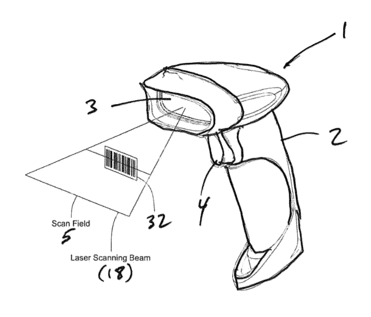
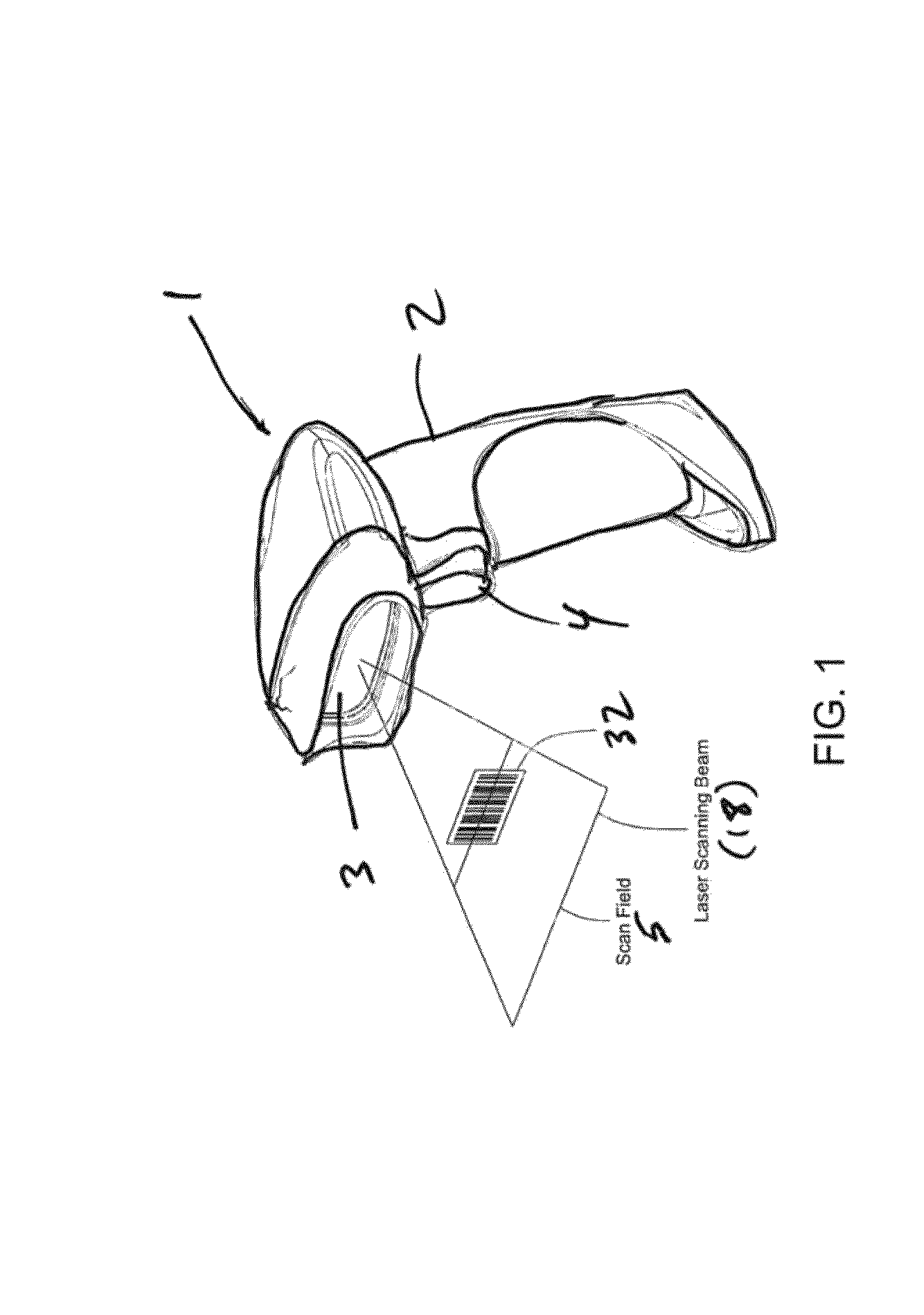
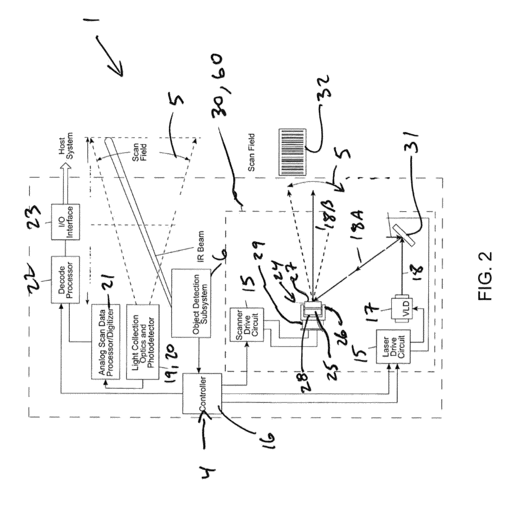
[0117]Laser scanning modules (i.e. engines) 30 and 60 are disclosed for use in diverse kinds of laser scanning bar code symbol reading systems 1 including, but not limited to, the hand-supportable laser scanning system 1 shown in FIG. 1. However, it is understood that these laser scanning modules 30 and 60 can be installed in other types of laser scanning systems, other than hand-supportable systems, such as POS-projection, countertop, and industrial type laser scanning systems.

[0118]As shown in FIGS. 1 and 2, the laser scanning bar code symbol reading system 1 comprises: a hand-supportable housing 2 having a head portion and a handle portion supporting the head portion; ...


PUM


Abstract

Laser scanning module employing a scan mirror and magnet rotor subassembly supported by a stationary stator structure. The scan mirror and magnet rotor subassembly includes: a silicone frame having a pair of silicone torsional hinges (i.e. posts) aligned along a scan axis and a supported by a pair of support elements associated with the stator structure, to support the scan mirror and magnet rotor subassembly. When the scan mirror and magnet rotor subassembly is rotated about its scan axis, by forces generated by an electromagnetic coil structure acting on the permanent magnet mounted on silicone frame, the silicone torsional hinges are elastically distorted and generate linear restoring forces which return the rotor subassembly back to its home position about the scan axis.

Description

BACKGROUND OF DISCLOSURE[0001]1. Field of Disclosure[0002]The present disclosure relates to improvements in laser scanning modules, and more particularly to improvements in laser scanning assemblies employed therein.[0003]2. Brief Description of the State of the Art[0004]The use of laser scanning bar code symbol reading engines is well known in the art. Applications include: hand-held products; reverse-vending machines; and the like.[0005]Currently, various types of laser scanning mechanisms have been developed for scanning laser beams across bar code symbols. Such laser scanning mechanisms include shaft-based laser scanning mechanisms; hinge-based laser scanning mechanisms; torsional-based laser scanning mechanisms; and flipper-based laser scanning mechanisms.[0006]Conventional shaft-based scanning mechanisms suffer from a number of shortcomings and drawbacks. In particular, prior art shaft-based scanning assemblies suffer from friction-related uncertainty and reliability problems....

Claims


Application Information

Patent Timeline
Patent Type & Authority Patents(United States)
IPC IPC(8): G06K19/00
CPCG06K7/10633G02B26/105G06K2007/10485
Inventor FENG, CHENRUEBLINGER, GREGORYWANG, YNJIUN PAUL
Owner METROLOGIC INSTR
Why Eureka
Try Eureka