
Process of making a component with a passageway

a manufacturing process and passageway technology, applied in the field of components, can solve the problems of high cost of polymer parts, inability to cool these very hot lamps, and high cost of lower volume production of polymeric parts, so as to save hundreds of thousands of dollars and many weeks of die manufacturing time, and increase manufacturing speed. , the effect of quick and inexpensive design

Inactive Publication Date: 2014-12-23
A RAYMOND & CO
View PDF125 Cites 44 Cited by
  • Summary
  • Abstract
  • Description
  • Claims
  • Application Information

AI Technical Summary

Benefits of technology

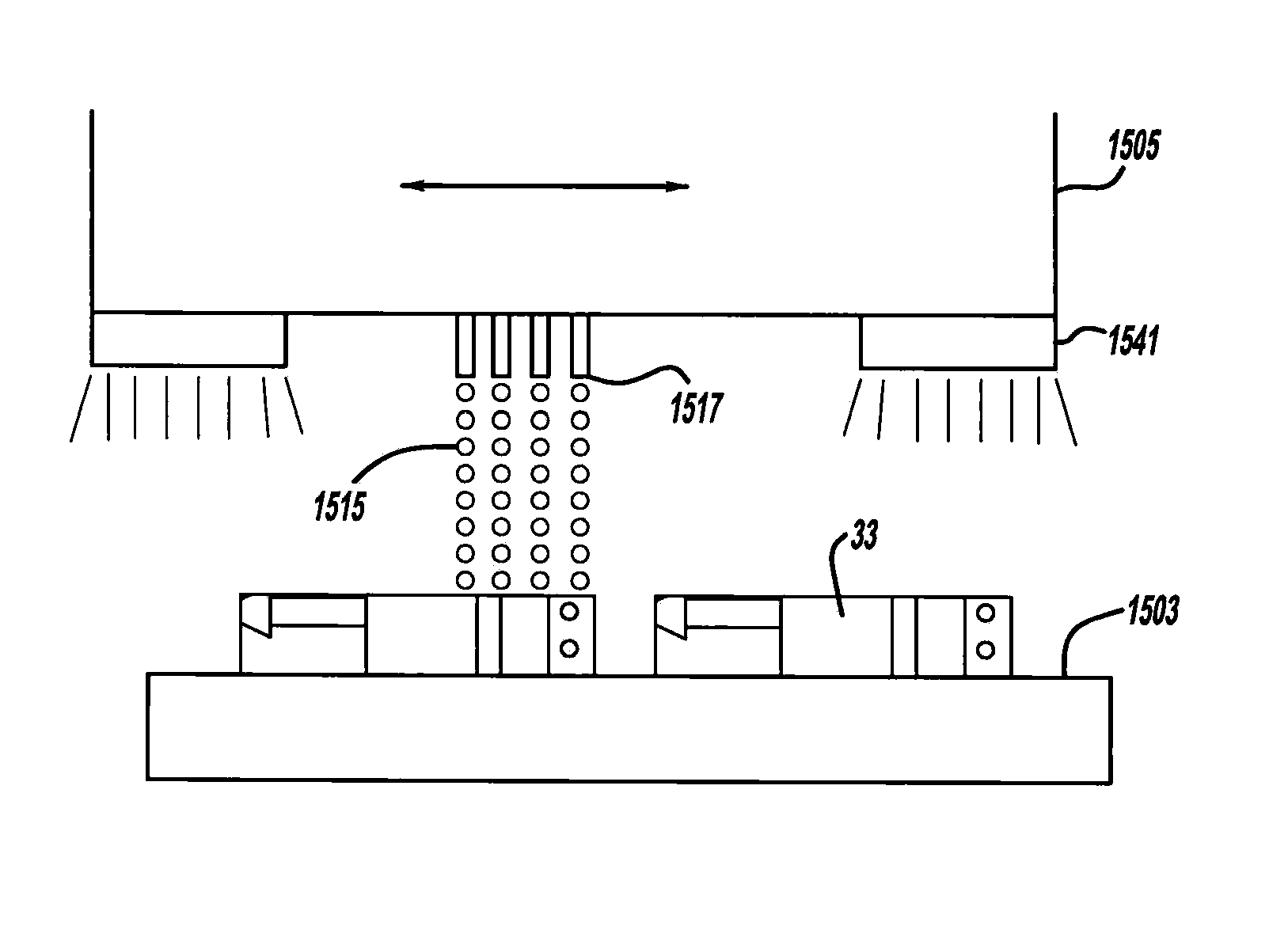
The present invention provides a method for manufacturing components with internal passages, such as washer jets and lamps, without the need for expensive and time-consuming traditional tooling or dies. The method uses a three-dimensional printing machine to emit material from an ink jet printing head to build up the component layer by layer. The method is advantageous over traditional methods as it allows for quick and inexpensive design and part revisions, and it also reduces post-manufacturing assembly by creating mating parts in a pre-installed or pre-assembled condition within the same manufacturing machine cycle. The present invention can make at least ten, and more preferably at least forty, identical components in a single manufacturing cycle. The method also allows for the creation of die-locked part configurations that would otherwise be prohibitively expensive. The present invention is also advantageous in that it can make use of stereolithography and other advanced manufacturing techniques to create components with internal passages that were previously only possible with die-locked configurations.

Problems solved by technology

These traditional manufacturing processes, however, disadvantageously require very expensive machined steel dies, which are difficult and time consuming to modify if part revisions are desired, and are subject to problematic part-to-part tolerance variations.
Such variations are due to molding shrinkage during curing, molding pressure differences, part warpage due to internal voids and external sink marks, and the like.
The expense of this traditional die tooling makes lower volume production of polymeric parts prohibitively expensive.
These disadvantages are especially apparent for conventional automotive vehicle washer jets where multiple components need to be separately injection molded then assembled together to create the otherwise die-locked internal passageways.
It is problematic, however, to cool these very hot lamps.
Conventional light emitting diode lamps for automotive vehicles require very complicated and expensive constructions including coolant tubes running from a vehicle radiator to each lamp with a six piece lamp housing being machined from aluminum and then assembled together.
These parts are extremely slow to produce and impractically brittle.

Method used


Image

  • Process of making a component with a passageway
  • Process of making a component with a passageway
  • Process of making a component with a passageway

Examples


Embodiment Construction

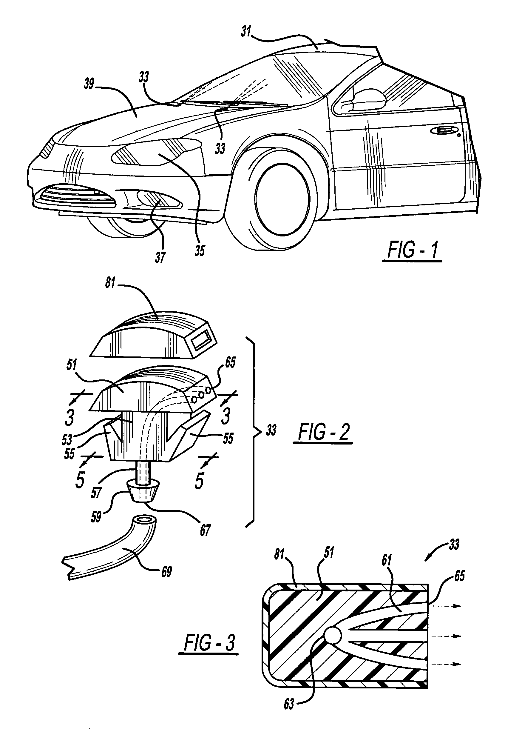
[0018]FIG. 1 illustrates an automotive vehicle 31 including various three-dimensionally printed components, including window washer jets 33 and lamps 35 and 37. Washer jets 33 are fastened to a vehicular body panel such as a hood 39 for a windshield use, or a roof or lift gate panel for a back window use. Exterior lamp 35 is mounted to an upper radiator support panel or front fender panel when acting as a head lamp, alternately to a tail panel or rear fender panel when acting as a tail lamp, and to a trunk lid or roof if acting as a center high mount stop lamp. The lamp may alternately serve as a fog or running lamp 37.

[0019]Referring to FIGS. 2 and 3, each washer jet 33 includes a laterally enlarged head 51, a body 53 longitudinally extending to a bottom of head 51, and a pair of wings 55 which are flexibly attached to lateral sides of body 53. Additionally, a rigid conduit 57 protrudes in a longitudinal direction from a distal end of body 53 with a generally frusto-conically shape...


PUM

PropertyMeasurementUnit
diameteraaaaaaaaaa
functionally durableaaaaaaaaaa
flexibleaaaaaaaaaa

Abstract

A component is provided that includes at least one passageway. In another aspect, a component, such as a lamp or a vehicular washer jet, is made of layers of material, a light curable material and / or multiple built-up materials. Another aspect uses a three-dimensional printing machine to emit material from an ink jet printing head to build up a component.

Description

BACKGROUND AND SUMMARY[0001]The present invention relates generally to components and more particularly to manufacturing of a component with a passageway.[0002]Traditionally, polymeric parts are made by injection or extrusion molding. In such processes, a heated polymeric liquid is inserted into match metal dies under high pressure, after which the dies are internally cooled in order to cure the manufactured parts. Air is vented from the die cavity when the molten polymer is injected therein. Injection and extrusion molding are ideally suited for high volume production where one hundred thousand or more parts per year are required. These traditional manufacturing processes, however, disadvantageously require very expensive machined steel dies, which are difficult and time consuming to modify if part revisions are desired, and are subject to problematic part-to-part tolerance variations. Such variations are due to molding shrinkage during curing, molding pressure differences, part wa...

Claims


Application Information

Patent Timeline
Patent Type & Authority Patents(United States)
IPC IPC(8): B29C35/08F21S8/10F21K99/00B29C67/00F21Y101/02F21V7/22B29C41/02F21V29/00
CPCB29C67/0062B29C67/0059F21Y2101/02F21V29/248B29C67/0055F21S48/325F21V7/22F21K9/13Y10T29/4998F21V29/58B60S1/52F21K9/23F21Y2115/10B29C64/112B29C64/124B33Y80/00B33Y10/00F21S45/465B29C64/106B29C64/182
Inventor JACKSON, NICHOLASHEMINGWAY, TODD L.PIPP, JR., WALTER B.
Owner A RAYMOND & CO
Learn More