Safe pressure system viewing port

a viewing port and pressure system technology, applied in the field of safe pressure system viewing port, can solve the problems of destroying the pane, destroying the pane, and expensive repair or replacement of such pumps and other equipment, and destroying the system

Inactive Publication Date: 2014-12-23
MANSOUR II JOSEPH ALEXANDER
View PDF6 Cites 4 Cited by
  • Summary
  • Abstract
  • Description
  • Claims
  • Application Information

AI Technical Summary

Problems solved by technology

Such vacuum systems often have expensive turbo pumps, ionization gauges, getter pumps, diffusion pumps, substrates and other materials which are susceptible to damage from any component of air such as oxygen or water vapor.
To repair or replace such pumps and other equipment can cost thousands to millions of dollars depending upon how complicated the system is.
The problem with directed high energy laser beams through a pane of transparent material is that such an act can cause destruction of the pane and breach of the vacuum integrity of the viewing port.
Debris ingestion can destroy or damage such pumps and engender high repair costs.
The failure mechanisms are varied, but can involve skin oil smudges on the transparent pane or dirt or dust which can cause uneven localized heating to very high temperatures in some spots compared to cooler regions of the pane adjacent to the spots which have been unevenly heated.
This can rupture the glass or cause a crack to start caused by rapid thermal expansion of one section of the transparent material relative to a cooler region adjacent the hot region.
A crack can eventually or immediately cause the pane to fail because of the forces acting on the pane because of the pressure difference between the vacuum in the chamber and the atmospheric pressure pushing on the pane from the outside.
Fractures can be dangerous and expensive and are to be avoided.

Method used


Image

  • Safe pressure system viewing port
  • Safe pressure system viewing port
  • Safe pressure system viewing port

Examples


Embodiment Construction

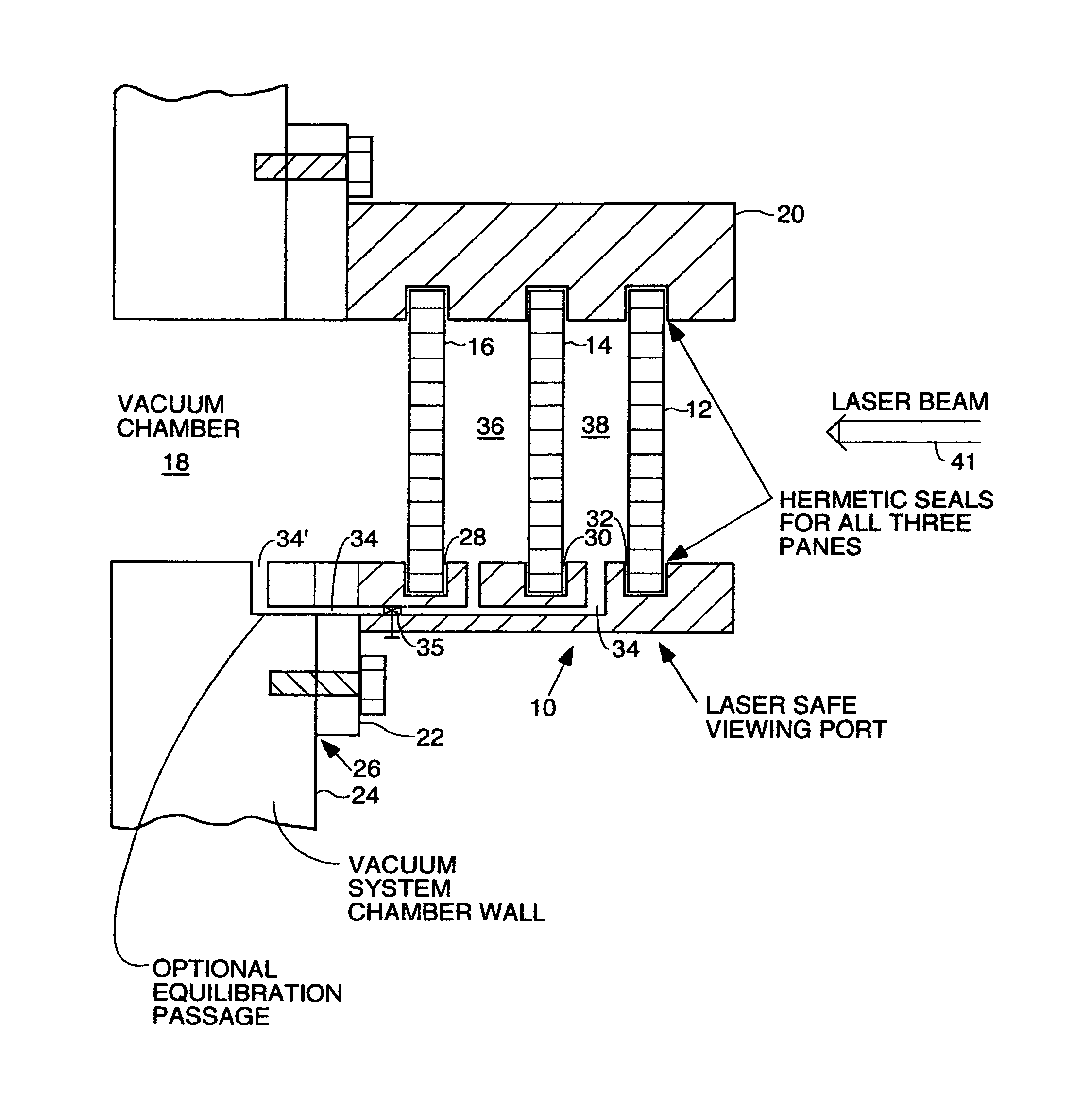
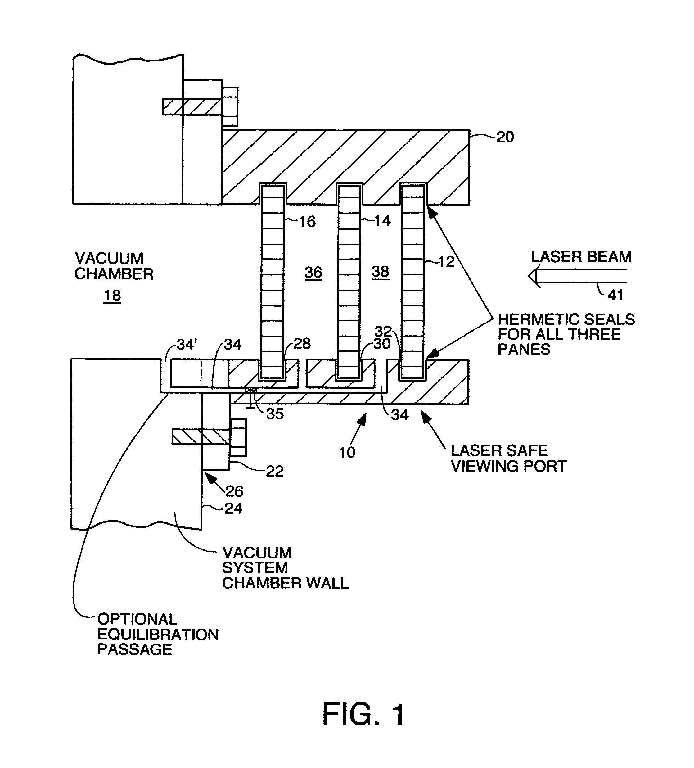
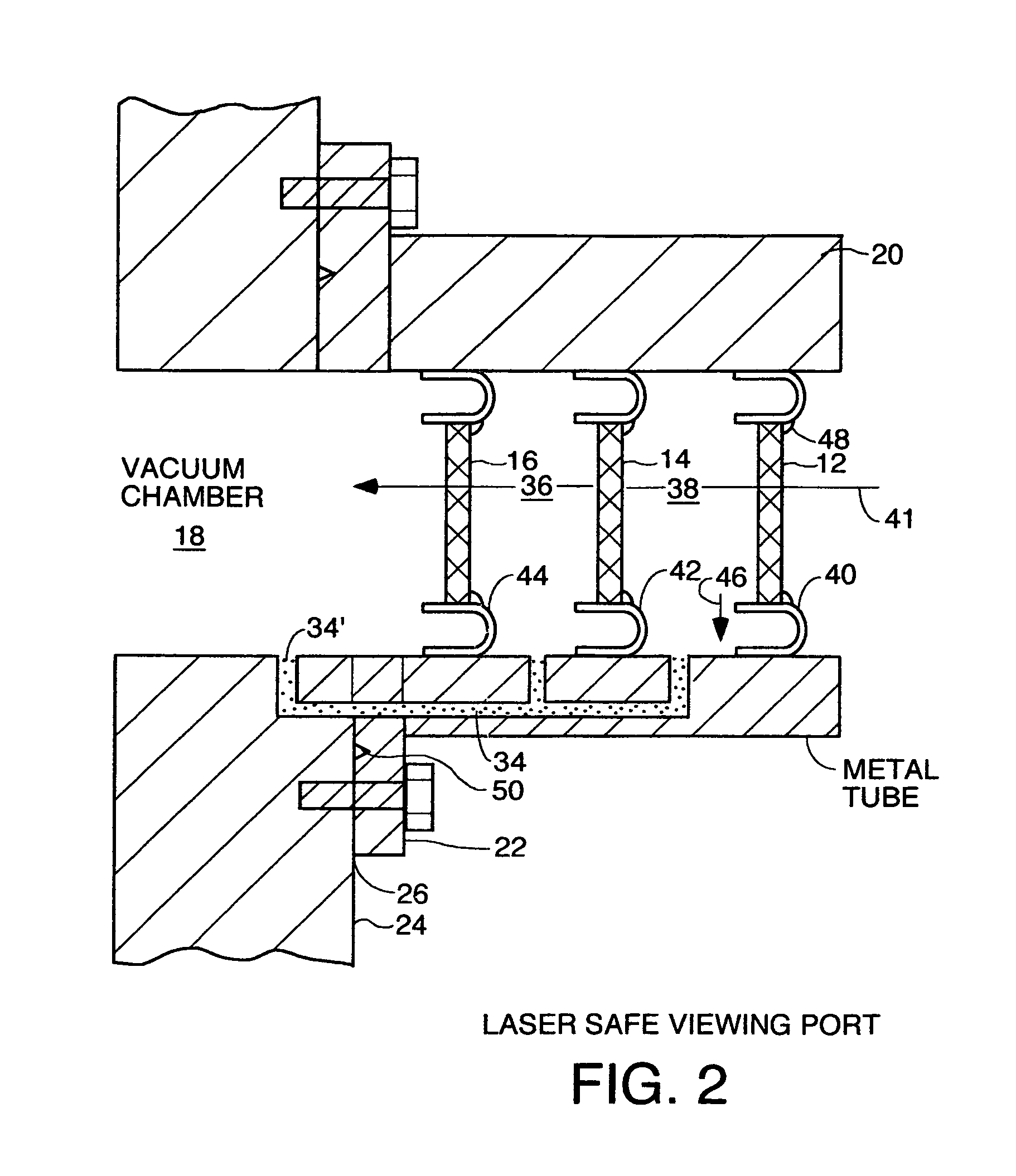
[0024]In the preferred embodiment, a safe viewing port is provided which is useful for vacuum or high pressure systems. In particular, the safe viewing port is fabricated so as to be less likely to fail when a high power laser beam is directed through it, or somehow a mechanical impact on the outer pane causes a crack or a crack forms from thermal cycling or stress or chemical attack or material imperfections in any of the multiple panes. In most embodiments, two or more panes of visibly transparent or electromagnetically transparent material which are spaced apart and hermetically sealed to a frame which itself is hermetically sealed to a port into the vacuum chamber of a vacuum system. The panes may be made of sapphire, quartz and glass, silicon, gallium arsenide, indium phosphide, polycarbonate, magnesium fluoride, calcium fluoride, zinc selenide, zinc sulfide, silicon carbide, gallium nitride, yittrium iron garnet, yittrium aluminum garnet, lithium niobate, lithium tantalate, Zn...


PUM


Abstract

A fracture-safe viewport for a pressure system having a pressure port which is pumped by said pressure system to a pressure above or below atmospheric pressure, comprising a plurality of panes each capable of passing electromagnetic radiation therethrough, each pane being mounted inside a tubular structure and being hermetically sealed to the wall of the pressure chamber. Each of the panes may be a different material or any combination of materials may be used from the group comprising sapphire, glass and quartz or any other material through which a high powered laser or other electromagnetic beam may be directed without adverse consequences. Highly pure, defect-free, ultra-polished, single-crystal sapphire is preferred. Spacing between the panes is used in most embodiments to avoid shrapnel damage in case of catastrophic failure of a pane. Half-donut shaped or chimney-shaped strain relief mounts are used in some embodiments to relieve strain caused by differential rates of thermal expansion when the structure is heated.

Description

BACKGROUND OF THE INVENTION[0001]Vacuum systems that can generate high vacuums are used for many purposes such as semiconductor manufacture, research experimentation in companies and universities, etc. Such vacuum systems often have expensive turbo pumps, ionization gauges, getter pumps, diffusion pumps, substrates and other materials which are susceptible to damage from any component of air such as oxygen or water vapor. For example, oxygen in inrushing air and reacts with heated surfaces or other heated materials and oxidizes them. To repair or replace such pumps and other equipment can cost thousands to millions of dollars depending upon how complicated the system is.[0002]Many such vacuum systems have viewing ports through which the experimenter or engineer interested in the process going on inside the vacuum system can look. Typically, these viewing ports are round metal structures surrounding a transparent pane of glass or other electromagnetically transparent material. The pa...

Claims


Application Information

Patent Timeline
Patent Type & Authority Patents(United States)
IPC IPC(8): E06B7/00B01J3/00F21V33/00E06B3/00H01L21/00G02B27/00
CPCB01J3/00B01J3/004H01L21/00
Inventor MANSOUR, II, JOSEPH, ALEXANDER
Owner MANSOUR II JOSEPH ALEXANDER
Why Eureka
Try Eureka