In situ synthesis of nanoparticles on substrates by inkjet printing

a nanoparticle and substrate technology, applied in the field of printing, can solve the problems of reducing throughput, low yield of nanoparticles with the desired, and high cost of pvd process operation, so as to improve the control of the deposition pattern and reduce cost

Active Publication Date: 2014-12-23
KING ABDULLAH UNIV OF SCI & TECH
View PDF7 Cites 0 Cited by
  • Summary
  • Abstract
  • Description
  • Claims
  • Application Information

AI Technical Summary

Benefits of technology

[0006]Nanoparticles may be synthesized with inkjet printing, or other type of printing, through a two-step process for depositing solution on a substrate. A first step involves depositing a first solution, and the second step involves depositing a second solution, in which the first and second solutions are precursors to nanoparticles. Nanoparticles may be formed through a chemical reaction, which occurs when the second solution mixes with the first solution. Methods for depositing nanoparticles from precursor solutions offer a number of advantages, including the versatility to print nanoparticles of different materials or sizes based on the selected first and second solutions, reduced cost by fully utilizing the first and second solutions, and improves control over the deposition pattern because nanoparticles only form where the first and second solutions mix.

Problems solved by technology

These processes are complex and result in low yield of nanoparticles with the desired composition, size, and size distribution.
Further, operation of PVD processes is expensive and generates relatively low throughput.
Loading substrates into chambers and evacuating air from the chamber to lower the pressure into the operational range for the PVD process requires time, which reduces throughput.
Further, the deposition process is relatively uncontrolled and may result in wasted materials.
Thus, if the materials are expensive, such as when gold nanoparticles are deposited, the wasted material may represent a large expense.
For example, the preparation of the stable ink solution is difficult and requires significant preparation time and purification before printing the ink with the inkjet printer.
Moreover, infiltration of a porous medium is limited to the size of the nanoparticles used.

Method used


Image

  • In situ synthesis of nanoparticles on substrates by inkjet printing
  • In situ synthesis of nanoparticles on substrates by inkjet printing
  • In situ synthesis of nanoparticles on substrates by inkjet printing

Examples


Embodiment Construction

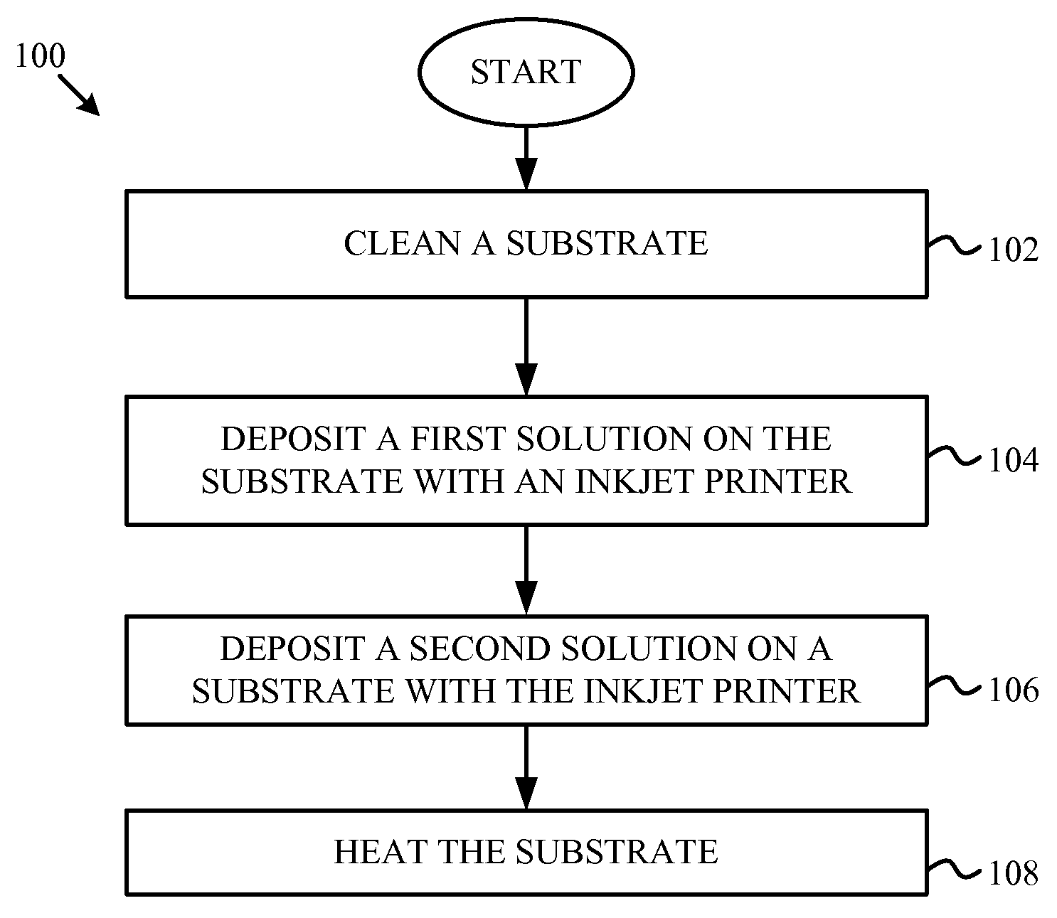
[0017]FIG. 1 is a flow chart illustrating a method 100 for depositing nanoparticles on a substrate with inkjet printing according to one embodiment of the disclosure. Method 100 begins at block 102 with cleaning a substrate. The substrate may be one of rigid or flexible substrates, such as silicon, glass, indium tin oxide (ITO), metal, textile, paper, and polyimide. The substrate may also be a combination of these materials and / or similar materials, such as a substrate having a silicon oxide layer deposited on a silicon base. Cleaning the substrate may include one or more of rinsing the substrate with water, drying the substrate, rinsing with substrate in ethanol with ultrasonic agitation, rinsing the substrate in acetone with ultrasonic agitation, rinsing the substrate in isopropanol alcohol with ultrasonic agitation, and drying the substrate.

[0018]At block 104, a first solution is deposited on the substrate with an inkjet printer. The inkjet printer may be a piezoelectric drop-on-...


PUM

PropertyMeasurementUnit
temperaturesaaaaaaaaaa
diameteraaaaaaaaaa

Abstract

Nanoparticles may be formed on a substrate by mixing precursor solutions deposited by an inkjet printer. A first solution is deposited on a substrate from a first inkjet print cartridge. Then, a second solution is deposited on the substrate from a second inkjet print cartridge. The solutions may be printed in an array of droplets on the substrate. Nanoparticles form when droplets of the first solution overlap with droplets of the second solution. In one example, the nanoparticles may be gold nanoparticles formed from mixing a first solution of 1,2-dichlorobenzene (DCB) and oleylamine and a second solution of gold chloride trihydrite and dimethyl sulfoxide (DMSO). The nanoparticles may be incorporated into optoelectronic devices.

Description

CROSS-REFERENCE TO RELATED APPLICATIONS[0001]This application claims the benefit of priority of U.S. Provisional Patent Application No. 61 / 650,375 to Mutalifu Abulikemu and Ghassan Jabbour filed on May 22, 2012 and entitled “In Situ Synthesis of Nanoparticles on Substrates by Inkjet Printing,” which is hereby incorporated by reference in its entirety.FIELD OF THE DISCLOSURE[0002]This invention relates to printing and more particularly relates to in-situ ink jet synthesis of nano particles.BACKGROUND[0003]Nanoparticles, and particularly gold nanoparticles, have unique physical and chemical properties. These properties have increased interest in improving nanoparticles synthesis and creating commercially-feasible processes. Conventionally, nanoparticles are deposited using physical vapor deposition (PVD) methods, such as co-evaporation and co-sputtering.[0004]These processes are complex and result in low yield of nanoparticles with the desired composition, size, and size distribution....

Claims


Application Information

Patent Timeline
Patent Type & Authority Patents(United States)
IPC IPC(8): H01L33/06H01L33/00H01L21/02H01L33/16H01L31/18H01L33/28
CPCH01L21/0237H01L33/28H01L33/06H01L31/18H01L21/02543H01L21/02568H01L33/005H01L33/16H01L21/02601Y10S977/892H01L21/02628
Inventor ABULIKEMU, MUTALIFUJABBOUR, GHASSAN
Owner KING ABDULLAH UNIV OF SCI & TECH
Why Eureka
Try Eureka