
Wind turbine blade provided with optical wind velocity measurement system

a wind turbine and optical wind technology, applied in the field of wind turbines, can solve the problems of increasing mechanical loads from strong winds and fluctuations, changing blade loads, and already too late to fully compensate for load changes, so as to achieve the effect of preparing to prob

Active Publication Date: 2014-12-23
LM GLASSFIBER
View PDF11 Cites 5 Cited by
  • Summary
  • Abstract
  • Description
  • Claims
  • Application Information

AI Technical Summary

Benefits of technology

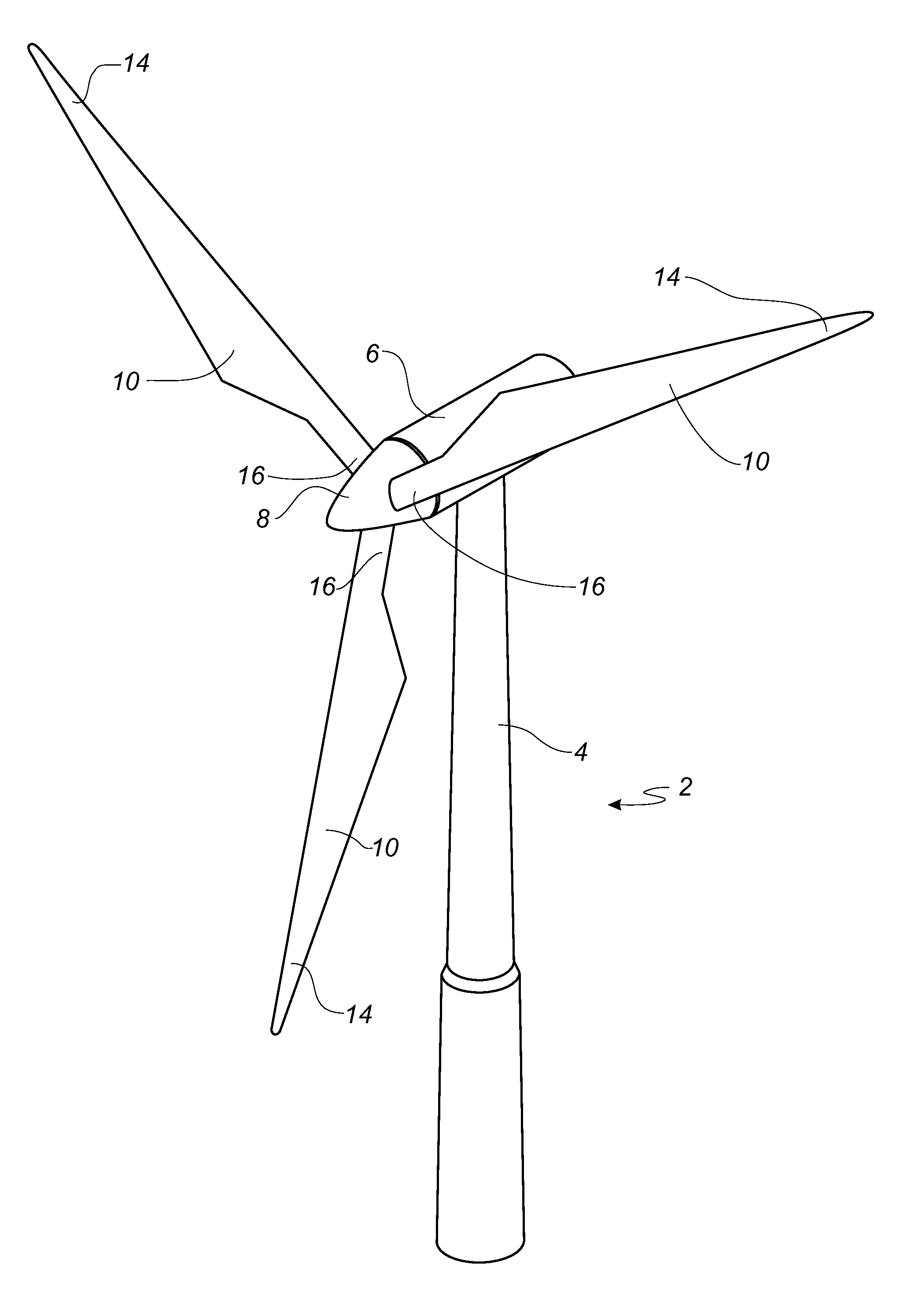
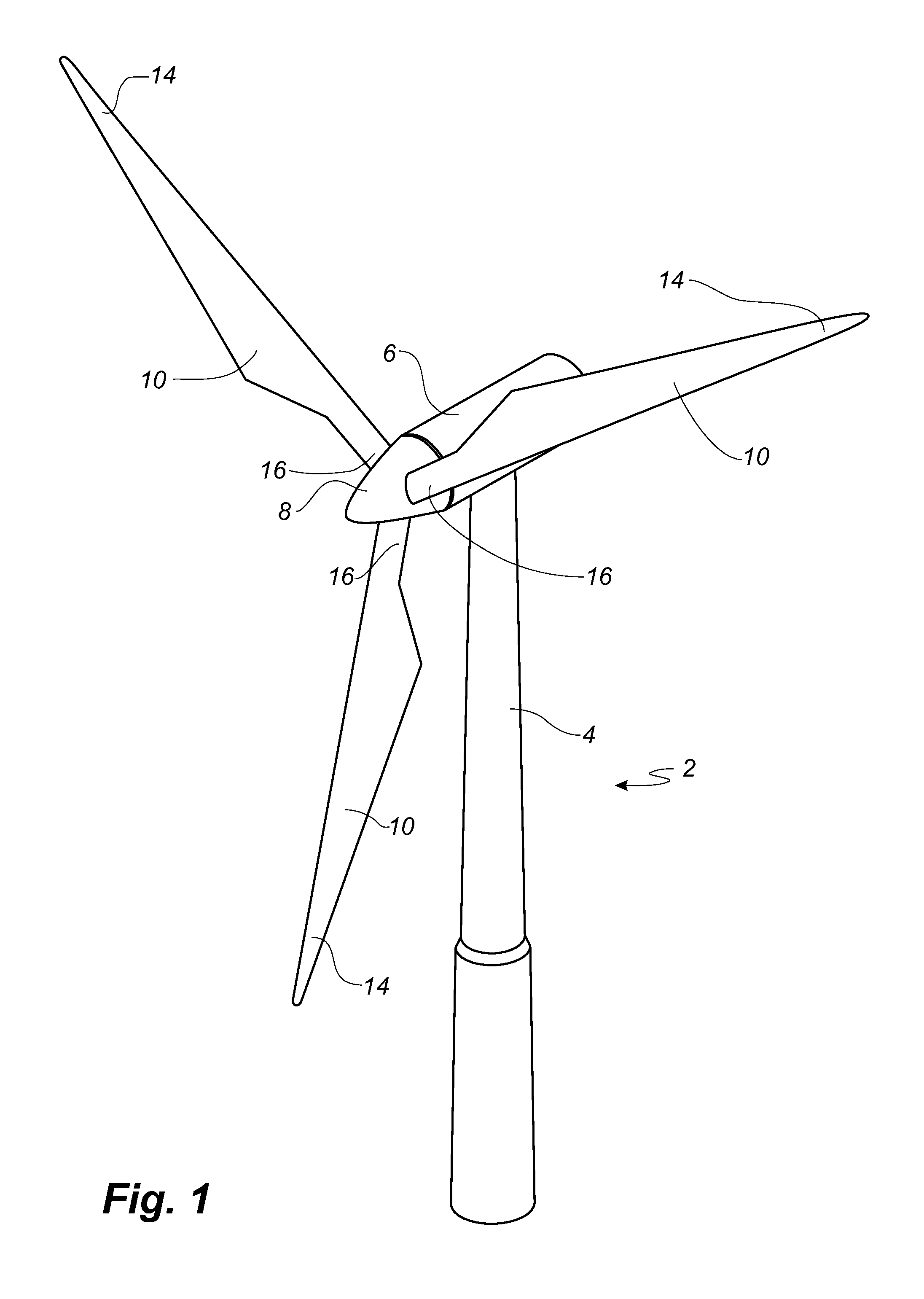
[0013]According to a first aspect of the invention, the emission point of the optical transmitter part is located in the first blade at a first radial distance from the centre axis, and the receiving point of the optical transmitter part is located in the first blade at a second radial distance from the centre axis. In this way, the wind turbine facilitates an optical measurement system, such as a LIDAR (Light Detection And Ranging) system, for measuring at least a first parameter of an inflow, such as wind speed or wind direction, locally at the first wind turbine blade. The optical emitting means and receiving means together define a probing region or probing volume, in which a measurement may be made.
[0054]According to another advantageous embodiment, the first wind turbine blade is pitchable, and the probing direction is variable in dependence on a pitch angle of the first blade. Thereby, it is for instance possible to adjust the probing direction so that the probing region does not change despite of the blade pitch being changed and / or in order to maximise the resolution of the probed wind speeds. Similarly, the probing direction may be variable in dependence on a rotational speed of the rotor.

Problems solved by technology

The increase in length also leads to increased mechanical loads from strong winds and from fluctuations in the wind.
This in turn causes pressure changes over the surface of the wind turbine blade, which finally changes the loads on the blade.
However, once the effect on the load is detected, it is already too late to fully compensate for the load changes.
However, such pitot tubes influence the flow characteristics of the blade, and furthermore pitot tubes may act as a lightning receptor, thus attracting lightning strikes potentially damaging the wind turbine blade.
However, the wind is non-uniform over the length of a wind turbine blade due to turbulence, tower shadow, wind shear, yaw errors, wake effects and the like.
This non-uniformity causes varying forces along the blades, which is turn cause fatigue loads and extreme loads on the wind turbine.
To compensate for such fluctuations it is not sufficient to obtain a single measurement hundreds of meters in front of the rotor.
However, the document does not provide any details on how such an anemometer should be mounted to the blade and where exactly the anemometer should probe the wind speed.
However, the document does not provide any details on where and how to arrange the anemometer.

Method used


Image

  • Wind turbine blade provided with optical wind velocity measurement system
  • Wind turbine blade provided with optical wind velocity measurement system
  • Wind turbine blade provided with optical wind velocity measurement system

Examples


first embodiment

[0083]FIG. 4 shows a schematic view of a wind turbine blade 10 according to the invention. The wind turbine blade 10 has the shape of a conventional wind turbine blade and comprises a root region 30 closest to the hub, a profiled or an airfoil region 34 furthest away from the hub and a transition region 32 between the root region 30 and the airfoil region 34. The blade 10 comprises a leading edge 18 facing the direction of rotation of the blade 10 when the blade is mounted on the hub, and a trailing edge 20 facing the opposite direction of the leading edge 18.

[0084]The airfoil region 34 (also called the profiled region) has an ideal or almost ideal blade shape with respect to generating lift, whereas the root region 30 due to structural considerations has a substantially circular or elliptical cross-section, which for instance makes it easier and safer to mount the blade 10 to the hub. The diameter (or the chord) of the root region 30 is typically constant along the entire root area...

second embodiment

[0096]FIG. 6b shows a second embodiment illustrating a possible probing direction of the system. During rotation of the rotor a LDA system 480 located within a wind turbine blade of the rotor follows a motion along a concentric circle 425 having a radius from a central axis of the rotor 415. In this embodiment, the LDA system 480 emits a probing beam (or beams) in an inwards direction out of the cross-sectional plane of the local profile at the LDA system 480. The probing region is in this embodiment located at the same radial distance from the central axis 415 as the emission point. Thus, the system may more accurately probe the wind speeds of particles, which the local blade section in fact impacts.

third embodiment

[0097]FIG. 6c shows a third embodiment illustrating a possible probing direction of the system corresponding to the embodiment shown in FIG. 5c. During rotation of the rotor an LDA system 1080 located within a first wind turbine blade 1010 of the rotor follows a motion along a concentric circle 1025 having a radius from a central axis of the rotor 1015. In this embodiment, the LDA system 1080 emits a probing beam (or beams) in an inwards direction out of the cross-sectional plane of the local profile at the LDA system 1080. The probing beam(s) are emitted from a location in vicinity of the trailing edge of the first blade 1010 and the probing region is located in front of the leading edge of a second wind turbine blade 1010′. The probing region is in this embodiment located in the same radial distance from the central axis 1015 as the LDA system 1080. The probing direction may also be substantially tangentially to the concentric circle 1025.


PUM


Abstract

A wind turbine includes a number of blades and an optical measurement system comprising a light source, such as a laser, an optical transmitter part, an optical receiver part, and a signal processor. The light source is optically coupled to the optical transmitter part, which includes an emission point for emitting light in a probing direction. The optical receiver part comprises a receiving point and a detector. The optical receiver part is adapted for receiving a reflected part of light from a probing region along the probing direction and directing the reflected part of light to the detector to generate a signal used to determine a first velocity component of the inflow. The emission point is located in a first blade at a first radial distance from a center axis, and the receiving point is located in the first blade at a second radial distance from the center axis.

Description

[0001]This is a National Phase Application filed under 35 U.S.C. 371 as a national stage of PCT / EP2010 / 068301 filed Nov. 26, 2010, and claims priority benefit from European Application No. 09177500.7, filed Nov. 30, 2009, the content of each of which is hereby incorporated by reference in its entirety.TECHNICAL FIELD[0002]The present invention relates to a wind turbine comprising a number of blades including at least a first wind turbine blade extending substantially radially from a hub on a main shaft having a substantially horizontal centre axis, the blades together with the hub constituting a rotor with a rotor plane, and which can be put into rotation by wind, and each blade having an innermost part comprising a root section of the blade and an outermost part comprising a tip section of the blade, wherein the wind turbine comprises an optical measurement system comprising a light source, such as a laser, an optical transmitter part, an optical receiver part, and a signal process...

Claims


Application Information

Patent Timeline
Patent Type & Authority Patents(United States)
IPC IPC(8): F03D7/02G01P3/36
CPCF05B2260/82F03D7/0224F05B2270/804Y02E10/723F03D7/0232F05B2270/326F05B2270/32F05B2270/8042G01P5/26F03D7/042Y02E10/72
Inventor FUGLSANG, PETERFUGLSANG, LARSHAMMER, LARS CHRISTIAN HVIDEGAARD
Owner LM GLASSFIBER
Learn More