Method for detecting single phase grounding fault based on harmonic component of residual current

a single-phase grounding fault and harmonic component technology, applied in short-circuit testing, emergency protective circuit arrangements, instruments, etc., can solve problems such as increased cost and complexity of detection systems, line error detection of grounding faults, and inability to provide voltage signals between outgoing lines of some real systems

Active Publication Date: 2014-12-23
TSINGHUA UNIV +1
View PDF13 Cites 8 Cited by
  • Summary
  • Abstract
  • Description
  • Claims
  • Application Information

AI Technical Summary

Benefits of technology

[0032]The detection objects of the invention are still the fundamental component and the harmonic component of the current. Similar to the traditional high impedance grounding detection method, it also focuses on the waveform distortion caused by the high resistance grounding fault, but it does not require the voltage signal as the comparison element. It just compares the harmonic component with the fundamental component, where the fundamental component is used as the reference element of direction comparison and the harmonic component is used as the element to be compared so as to achieve the above-mentioned harmonic analysis and direction distinguishing.
[0033]Thus, the present invention has overcome the disadvantages that the traditional over-current protection fails to distinguish the direction without the voltage signal, and succeeds in detecting the high impedance grounding fault, and is a practical and low-cost improvement and supplement to the traditional grounding fault detection based on the simple over-current theory.

Problems solved by technology

Consequently, the fault current caused by the fault line also flows through the circuit constituting of the sound line capacitance to ground, resulting that the detecting and protecting device in the sound line has an error detection of grounding fault because of the residual current increase.
The rendered problem is that protecting or detecting device needs to measure simultaneously the voltage and the current on the primary side of the system.
Nevertheless, on one hand, the voltage signal is not available between the outgoing lines of some real systems, and thus only a simple over current is applied to detect the grounding fault.
On the other hand, a detecting system will increase in its cost and complexity if introducing the voltage signal transformed from a voltage transformer.
Another problem in detecting the grounding fault is to detect the single phase grounding fault in the system with the transformer neutral point grounding via high-impedance resistors.
Because of the high impedance of the fault circuit in the system with the neutral point grounding via high-impedance resistors, the fault current is limited below the operation threshold of the traditional over-current protection.
It would be infeasible to detect the fault just with the amplitude.
However, these high impedance detection methods still need both the voltage signal and the current signal.

Method used


Image

  • Method for detecting single phase grounding fault based on harmonic component of residual current
  • Method for detecting single phase grounding fault based on harmonic component of residual current
  • Method for detecting single phase grounding fault based on harmonic component of residual current

Examples


embodiment 1

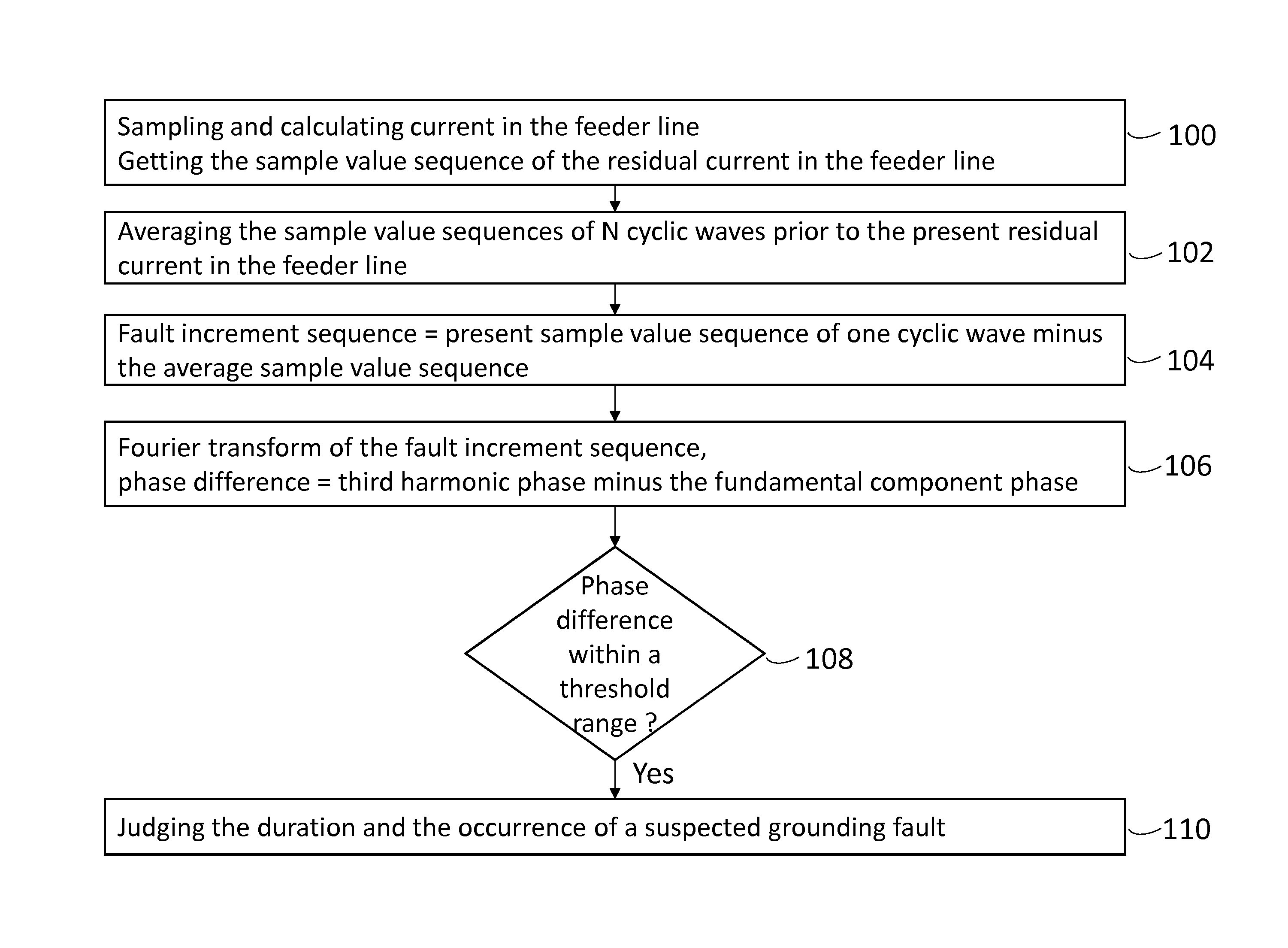
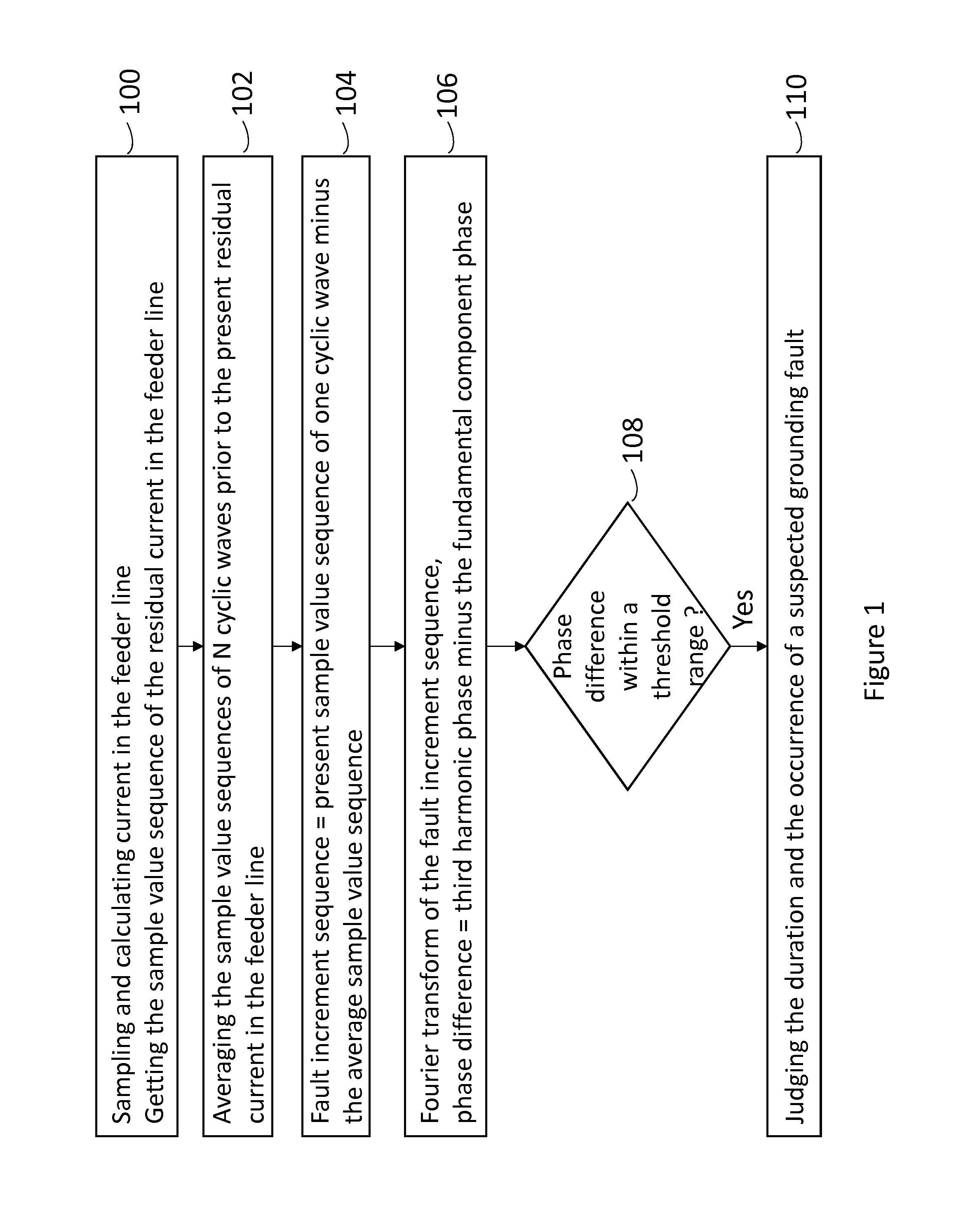
[0034]Embodiment 1 only needs to sample the residual current in the feeder line, without sampling the residual current at the neutral point. The working steps are as follows:

[0035]1) continuously sampling and calculating the current in the feeder line, and getting the sample value sequence of the residual current in the feeder line (achieved with the conventional detecting devices in the feeder line);

[0036]2) averaging the sample value sequences of six cyclic waves prior to the present residual current in the feeder line, to get the average sample value sequence;

[0037]3) getting the fault increment sequence by the present sample value sequence of one cyclic wave minus the average sample value sequence;

[0038]4) calculating the third harmonic amplitude A3 and angular velocity α3 and the fundamental amplitude A1 and angular velocity α1 of the fault increment sequence with Fourier transform, and calculating the phase difference of the third harmonic component relative to the fundamental...
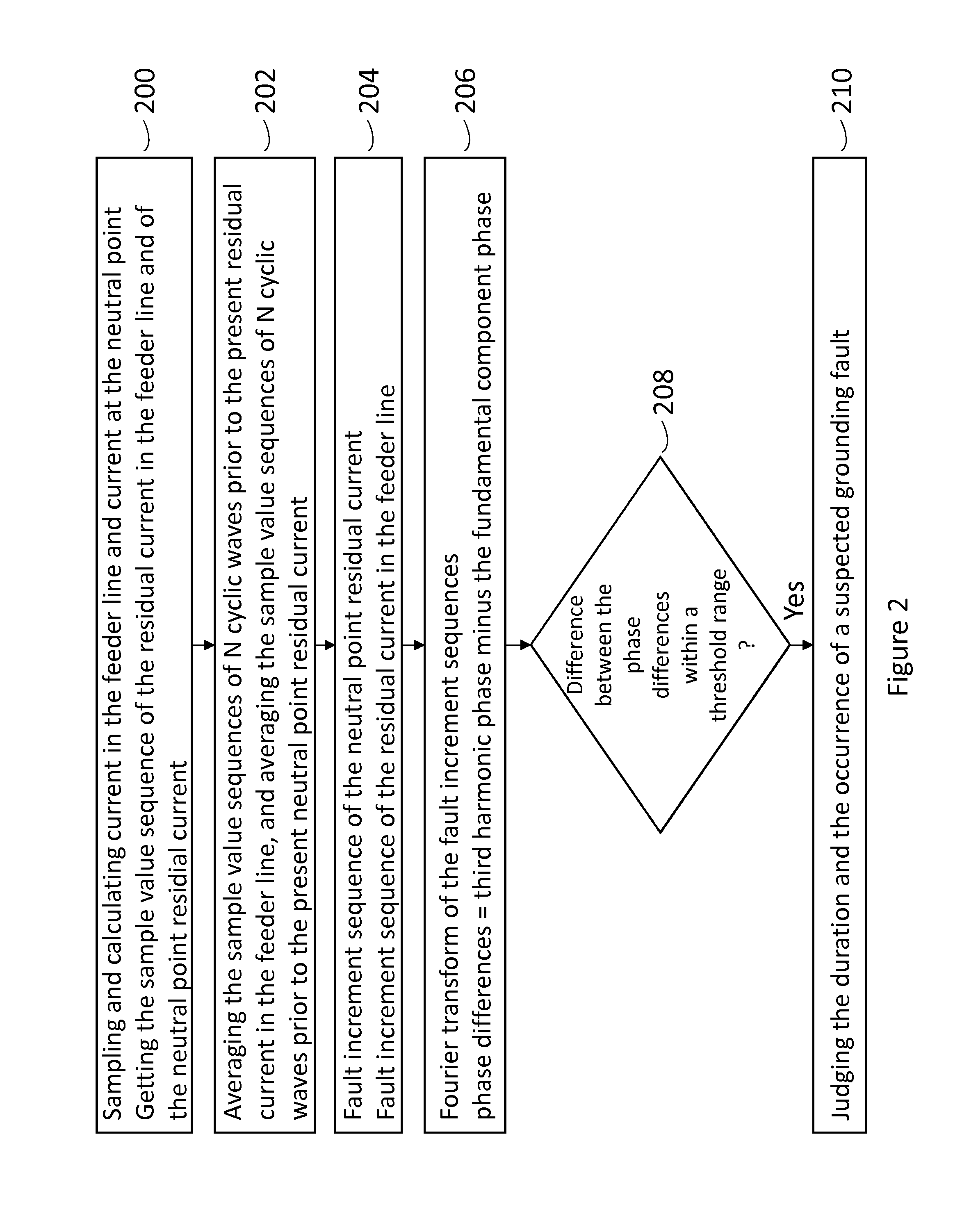
embodiment 2

[0049]The difference distinguishing embodiment 2 from embodiment 1 is to sample and use the residual current at the neutral point. Embodiment 2 determines the fault line according to the result of the phase difference of the residual current at the neutral point minus the phase difference of the residual current in the feeder line. This embodiment requires two conventional detecting devices, wherein one device directly detects the current flowing from the grounding point in the transformer substation into the earth, and the other detects the residual current in the feeder line of the same bus line in the transformer substation. Both detecting devices communicate to each other via the communication network.

[0050]The method of embodiment 2 is similar to the steps of embodiment 1, only adding the treatment of the residual current at the neutral point (treatment steps identical to those of residual current in the feeder line), and judging suspected grounding fault in step 5 according to...


PUM


Abstract

The method for detecting single-phase grounding fault based on the harmonic component of residual current is provided, in which collecting and calculating the phase differences of third harmonic waves relative to the fundamental wave of the residual current in the feeder line, and judging if the phase differences of the residual current in the feeder line is into a threshold range, and judging if there is a suspected grounding fault, and confirming the fault event by judging the duration and the generated times of the suspected grounding fault. Another method for detecting single-phase grounding fault based on the harmonic component of residual current is provided, in which the residual current of neutral point is used.

Description

CROSS REFERENCE TO RELATED APPLICATIONS OR PRIORITY CLAIM[0001]This application is a national phase of International Application No. PCT / CN2009 / 074606, entitled “METHOD FOR DETECTING SINGLE PHASE GROUNDING FAULT BASED ON HARMONIC COMPONENT OF RESIDUAL CURRENT”, which was filed on Oct. 26, 2009, and which claims priority of Chinese Patent Application No. 200810225056.1, filed Oct. 27, 2008.DESCRIPTION[0002]1. Field of the Invention[0003]The present invention relates to power system protection and control, more particularly, to line selection when medium voltage (10 kV˜66 kV) distribution line having radial connection and neutral resistance grounding occurs single phase grounding fault.[0004]2. Background of the Invention[0005]Single phase grounding fault is one of the most common faults in a distribution system. 6 kV-66 kV distribution network often makes the neutral point of the transformer ungrounded, or grounding via resistors or via an arc-extinguishing coil. The fault component ...

Claims


Application Information

Patent Timeline
Patent Type & Authority Patents(United States)
IPC IPC(8): H02H3/32G01R31/02G01R31/00H02H1/00
CPCG01R31/025H02H1/0092H02H3/32G01R31/52
Inventor DONG, XINZHOUCUI, TAO
Owner TSINGHUA UNIV
Why Eureka
Try Eureka