
Apparatus and method for a fuel nozzle

a technology of fuel nozzles and fuel nozzles, which is applied in the direction of forging/pressing/hammering apparatuses, lighting and heating apparatuses, machines/engines, etc., can solve the problems of low production efficiency, low efficiency, and high cost of manufacturing techniques

Active Publication Date: 2014-12-30
GENERAL ELECTRIC CO
View PDF27 Cites 10 Cited by
  • Summary
  • Abstract
  • Description
  • Claims
  • Application Information

AI Technical Summary

Benefits of technology

[0006]Aspects and advantages of the invention are set forth below in the following description, or may be obvious from the description, or may be learned through practice of the invention.

Problems solved by technology

However, these manufacturing techniques are relatively expensive, time-consuming, and otherwise less than optimum for large-scale production.

Method used


Image

  • Apparatus and method for a fuel nozzle
  • Apparatus and method for a fuel nozzle
  • Apparatus and method for a fuel nozzle

Examples


Embodiment Construction

[0015]Reference will now be made in detail to present embodiments of the invention, one or more examples of which are illustrated in the accompanying drawings. The detailed description uses numerical and letter designations to refer to features in the drawings. Like or similar designations in the drawings and description have been used to refer to like or similar parts of the invention.

[0016]Each example is provided by way of explanation of the invention, not limitation of the invention. In fact, it will be apparent to those skilled in the art that modifications and variations can be made in the present invention without departing from the scope or spirit thereof. For instance, features illustrated or described as part of one embodiment may be used on another embodiment to yield a still further embodiment. Thus, it is intended that the present invention covers such modifications and variations as come within the scope of the appended claims and their equivalents.

[0017]Embodiments of...


PUM

PropertyMeasurementUnit
inner diameteraaaaaaaaaa
temperatureaaaaaaaaaa
pressureaaaaaaaaaa

Abstract

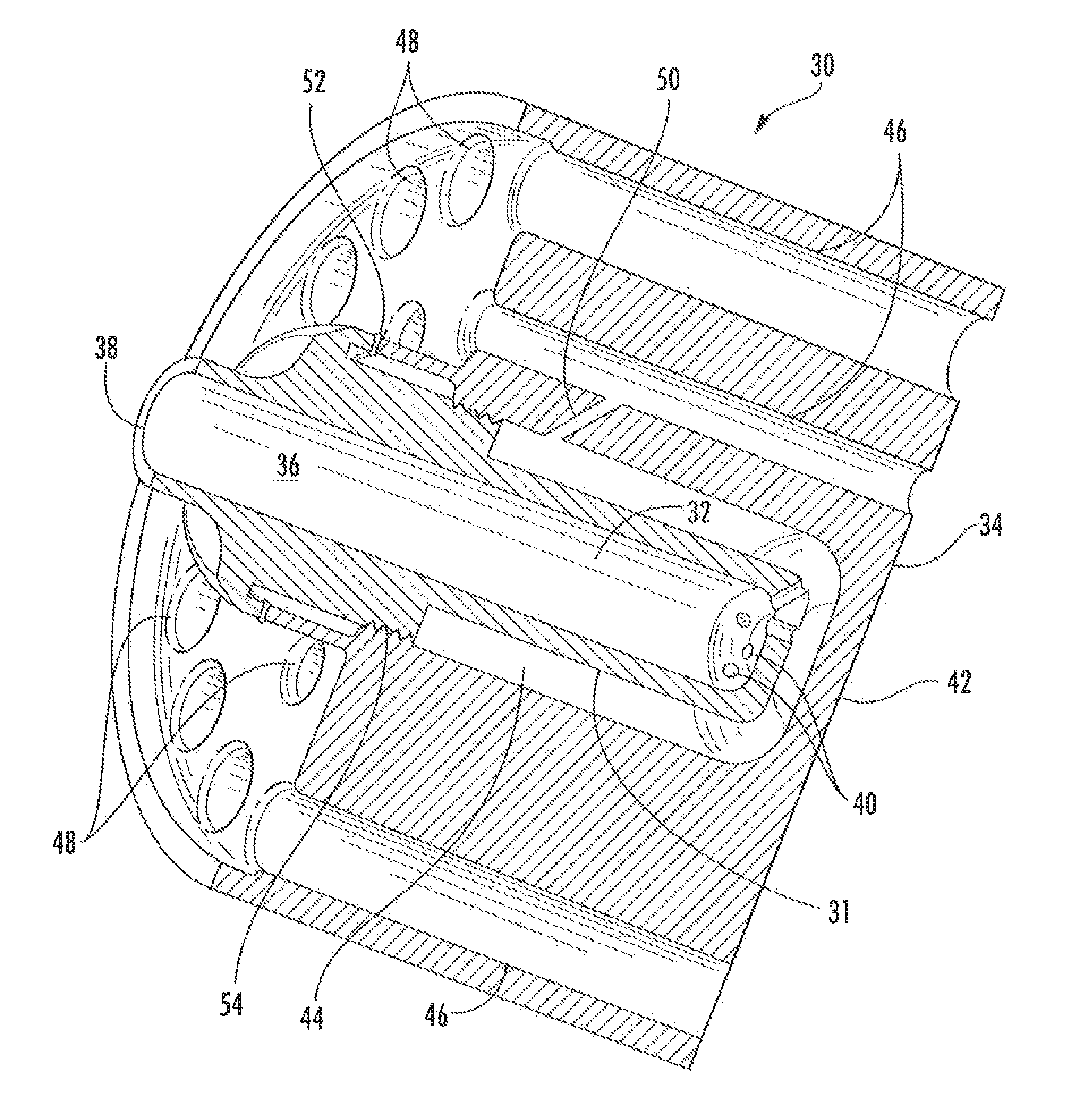
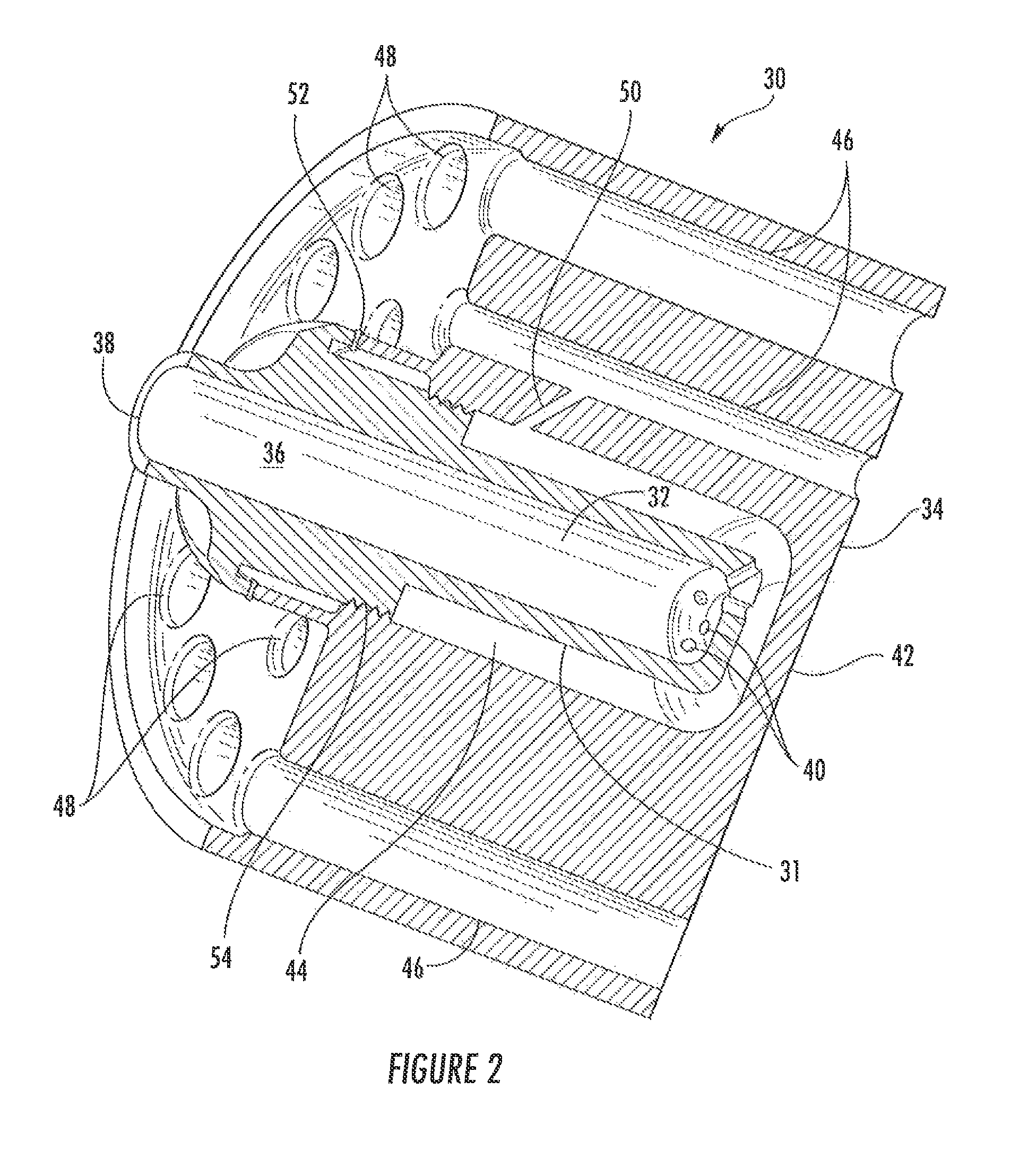
A fuel nozzle includes a fuel plenum, an outer body surrounding the fuel plenum, and bore holes that extend longitudinally through the outer body. The fuel nozzle also includes means for fixedly attaching the fuel plenum to the outer body and passages that provide fluid communication between the fuel plenum and the bore holes. A method for manufacturing a fuel nozzle includes drilling bore holes longitudinally through an outer body and drilling passages in the outer body to the bore holes. The method further includes inserting a fuel plenum into the outer body, wherein the passages provide a fluid communication between the bore holes and the fuel plenum, and attaching the fuel plenum to the outer body.

Description

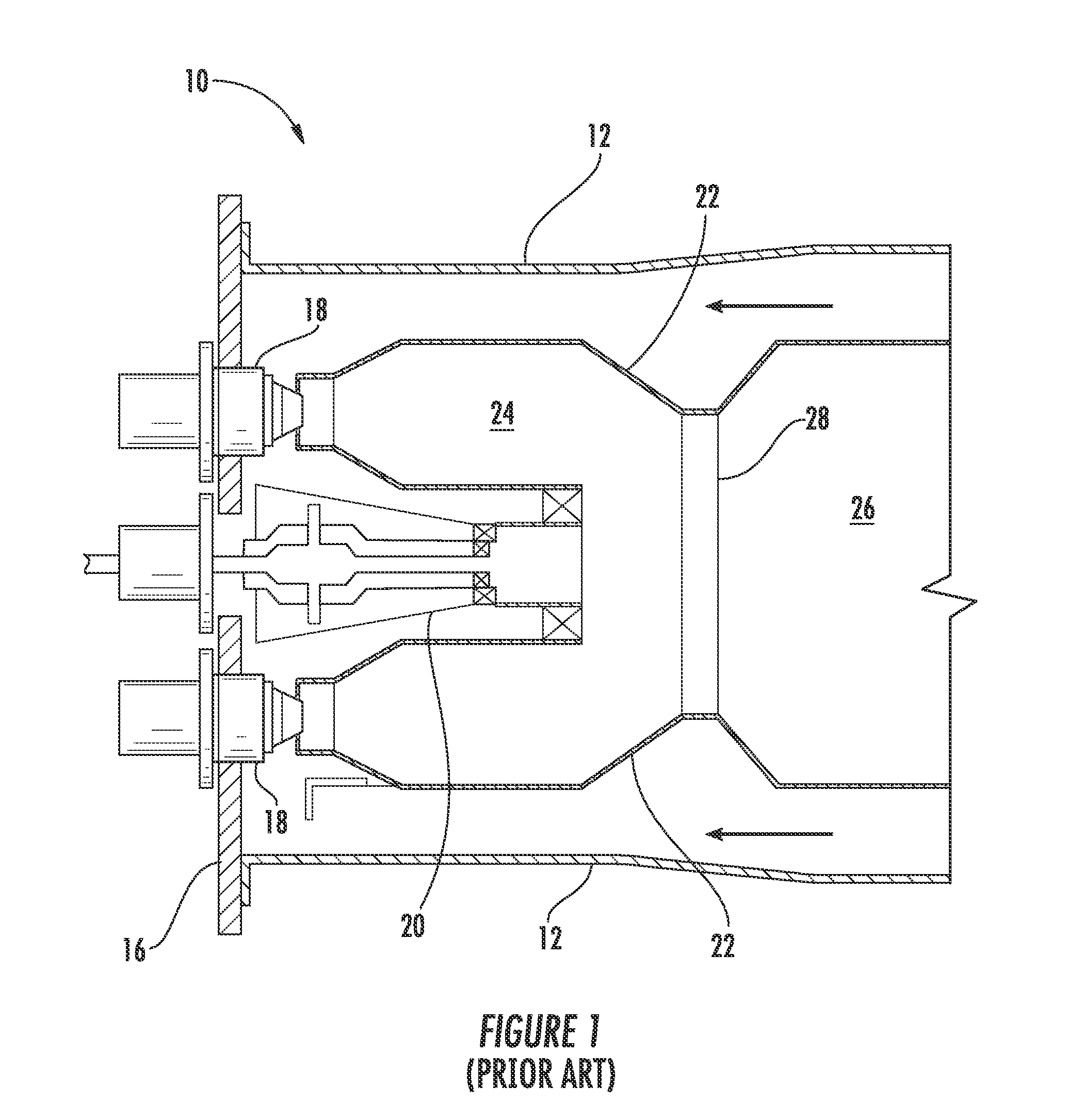
FIELD OF THE INVENTION[0001]The present invention relates generally to a fuel nozzle in a combustor and a method for making such a fuel nozzle.BACKGROUND OF THE INVENTION[0002]Combustors are widely used in commercial operations. For example, a typical gas turbine includes at least one combustor that injects fuel into the flow of a compressed working fluid and ignites the mixture to produce combustion gases having a high temperature and pressure. The combustion gases exit the combustor and flow to a turbine where they expand to produce work.[0003]FIG. 1 provides a simplified cross-section of a combustor 10 known in the art. A casing 12 surrounds the combustor 10 to contain the compressed working fluid. Nozzles are arranged in an end cover 16, for example, with primary nozzles 18 radially arranged around a secondary nozzle 20, as shown in FIG. 1. A liner 22 downstream of the nozzles 18, 20 defines an upstream chamber 24 and a downstream chamber 26 separated by a throat 28. The compres...

Claims


Application Information

Patent Timeline
Patent Type & Authority Patents(United States)
IPC IPC(8): F23R3/28B05B7/10F02G3/00F02M61/10F02C1/00
CPCF23R3/28Y10T29/49323F23R3/283F23R2900/00018F23R2900/03044
Inventor SUBRAMANIAN, KARTHIKROMIG, BRYAN WESLEY
Owner GENERAL ELECTRIC CO
Learn More