Fuel injection device for gas turbine

a technology of fuel injection device and gas turbine, which is applied in the direction of machines/engines, combustion types, lighting and heating apparatus, etc., can solve the problems of insufficient inability to achieve effective reduction of nox contained in exhaust gas after combustion, and non-uniform distribution of fuel concentration in the combustion chamber. achieve the effect of preventing thermal damage and speed reduction

Active Publication Date: 2016-06-16
KAWASAKI HEAVY IND LTD
View PDF39 Cites 8 Cited by
  • Summary
  • Abstract
  • Description
  • Claims
  • Application Information

AI Technical Summary

Benefits of technology

[0012]An object of the present invention is to provide a fuel injection device, for a gas turbine, which allows a distribution in concentration of fuel gas and water vapor in a combustion chamber to be made uniform with a simple structure and at low cost to effectively reduce generation of NOx.
[0020]In the fuel injection device according to the present invention, one of the first introduction passage and the second introduction passage may be arranged so as to introduce one of the fuel gas and the water vapor from an outer circumference of the nozzle housing in a radial direction of the mixing chamber, and the other of the first introduction passage and the second introduction passage may be arranged so as to introduce the other of the fuel gas and the water vapor into the mixing chamber in an axial direction of the nozzle housing. In this configuration, the fuel gas and the water vapor are introduced into the mixing chamber so as to form an angle of 90°, and the fuel gas and the water vapor thus collide with each other in the mixing chamber. Therefore, even before the fuel gas and the water vapor reach the reverse passage, the fuel gas and the water vapor are effectively mixed.

Problems solved by technology

However, in the fuel injection device disclosed in Patent Document 1, liquid fuel, water vapor, and gas fuel from the liquid fuel nozzle, the water vapor nozzle, and the gas fuel nozzle, are mixed in the combustion chamber only after the liquid fuel, the water vapor, and the gas fuel are injected into the combustor, and a distribution in concentration of the fuels and the water vapor in the combustion chamber thus becomes non-uniform, so that reduction of NOx contained in exhaust gas after combustion is insufficient.
However, a specific configuration therefor is not disclosed, and thus effective reduction of NOx contained in exhaust gas after combustion cannot be expected.
However, since liquid fuel is used as fuel, it is difficult to obtain a uniform distribution in concentration of the liquid fuel and the water vapor in the combustion chamber.
Therefore, substantial reduction of NOx is also difficult.

Method used


Image

  • Fuel injection device for gas turbine
  • Fuel injection device for gas turbine
  • Fuel injection device for gas turbine

Examples


Embodiment Construction

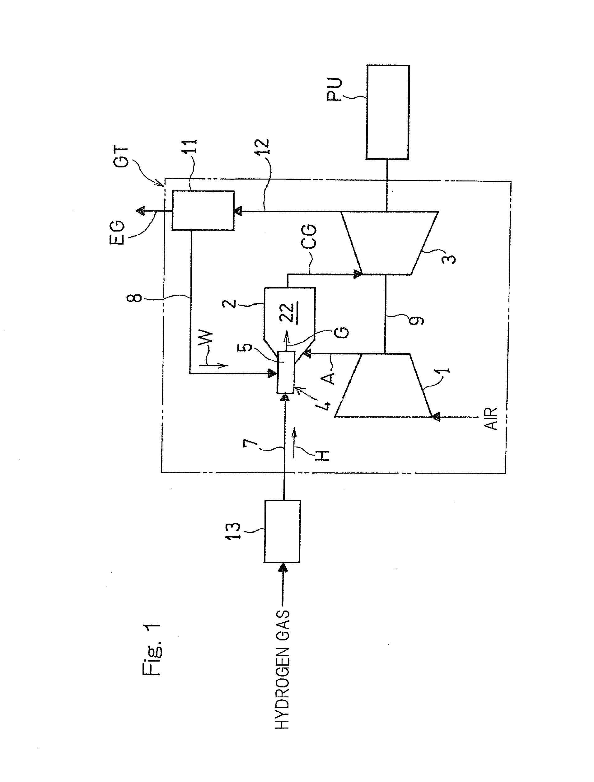
[0031]An embodiment of the present invention will be described below with reference to the drawings. FIG. 1 illustrates a gas turbine system to which a fuel injection device according to an embodiment of the present invention is applied. A gas turbine system GT shown in FIG. 1 includes: a compressor 1 configured to compress air A; a combustor 2; a turbine 3; and a boiler 11. The boiler 11 generates water vapor by using an exhaust gas EG discharged from the turbine 3 as a heat source.

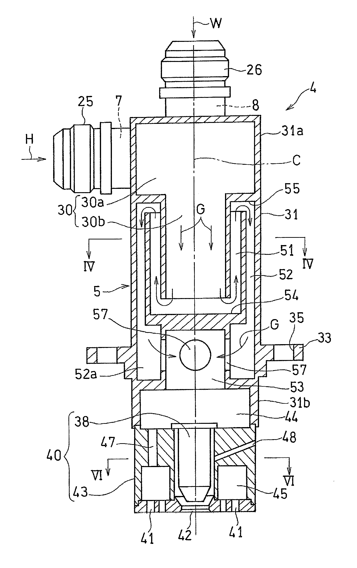
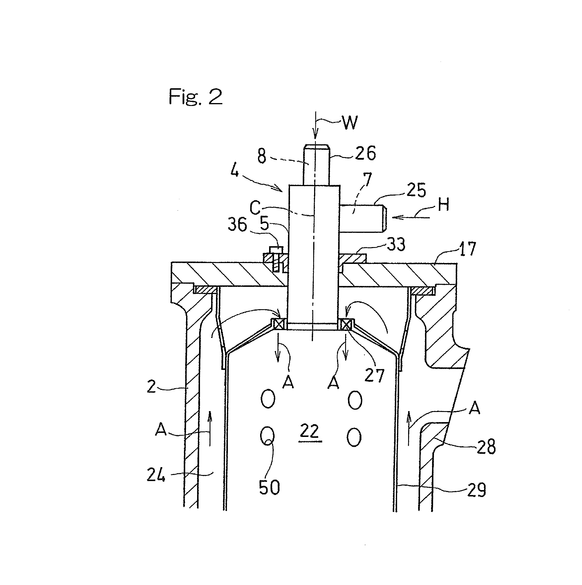
[0032]A fuel injection device 4 is provided at a head portion of the combustor 2. The fuel injection device 4 includes a fuel nozzle 5 having a base end portion on the upstream side thereof connected with a first introduction passage 7 through which fuel gas such as hydrogen gas H is supplied, and a second introduction passage 8 through which water vapor W from the boiler 11 is supplied. The water vapor W is supplied in order to reduce a flame temperature which is locally high in a combustion chamber 22 ...


PUM


Abstract

A fuel injection device, for a gas turbine, which enhances uniform distribution in concentration of fuel gas and water vapor in a combustion chamber with simple structure and at low cost to effectively reduce NOx, is provided. The fuel injection device with a fuel nozzle to mix fuel gas and water vapor and inject the fuel gas and water vapor into a combustion chamber, includes: a nozzle housing having a mixing chamber thereinside; a first introduction passage to introduce the fuel gas into the mixing chamber from outside of the nozzle housing; and a second introduction passage to introduce the water vapor into the mixing chamber from an outside of the nozzle housing; and a plurality of reverse passages communicating with a downstream end of the mixing chamber and configured to allow for a plurality of reverses of flow of mixed gas from the mixing chamber.

Description

CROSS REFERENCE TO THE RELATED APPLICATION[0001]This application is a continuation application, under 35 U.S.C. §111(a), of international application No. PCT / JP2014 / 072605, filed Aug. 28, 2014, which claims priority to Japanese patent application No. 2013-213506, filed Oct. 11, 2013, the disclosure of which are incorporated by reference in their entirety into this application.BACKGROUND OF THE INVENTION[0002]1. Field of the Invention[0003]The present invention relates to fuel injection devices, for gas turbines, which allow NOx in exhaust gas to be efficiently reduced by premixing fuel gas such as hydrogen gas, and water vapor so as to make a distribution in concentration thereof uniform before injection thereof into combustors.[0004]2. Description of Related Art[0005]In recent years, for gas turbine systems, a technique of injecting fuel and water or water vapor into a combustor in order to reduce generation of NOx in exhaust gas and enhance efficiency of the system, has been devel...

Claims


Application Information

Patent Timeline
Patent Type & Authority Applications(United States)
IPC IPC(8): F02M25/028F02C7/22F02M9/00
CPCF02M25/028F02C7/22F02M9/00F02C3/30F23R3/28F23R3/32F01K21/047F23L7/005F23C2900/9901F23D14/62F23R3/22F23R3/16F23R3/286
Inventor OKADA, KUNIOHORIKAWA, ATSUSHI
Owner KAWASAKI HEAVY IND LTD
Why Eureka
Try Eureka