
Fuel supply device for gas turbines and fuel nozzle and gas turbine having the same

a fuel supply device and gas turbine technology, which is applied in the direction of turbine/propulsion fuel supply systems, charge feed systems, combustion processes, etc., can solve the problems of increasing combustion temperature, nox generation, damage to the parts of the fuel nozzle, etc., and achieves the effect of reducing nitrogen oxides and stably burning fuel

Active Publication Date: 2019-09-19
DOOSAN HEAVY IND & CONSTR CO LTD
View PDF0 Cites 7 Cited by
  • Summary
  • Abstract
  • Description
  • Claims
  • Application Information

AI Technical Summary

Benefits of technology

The present patent aims to achieve a uniform fuel-air mixture in a combustion chamber to promote stable fuel burning and reduce nitrogen oxides production.

Problems solved by technology

Particularly, if the flow of air is not uniform, there is a concern that a flame may occur in a fuel nozzle, which may lead to damage to the parts of the fuel nozzle.
In addition, a non-uniform mixing of the air with fuel may increase combustion temperature or generate excessive NOx.

Method used


Image

  • Fuel supply device for gas turbines and fuel nozzle and gas turbine having the same
  • Fuel supply device for gas turbines and fuel nozzle and gas turbine having the same
  • Fuel supply device for gas turbines and fuel nozzle and gas turbine having the same

Examples


Embodiment Construction

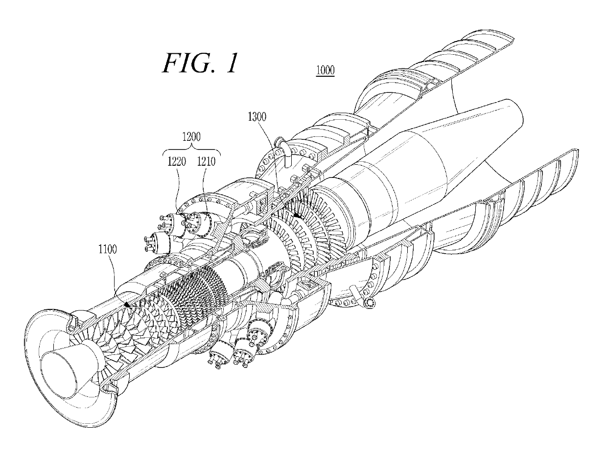
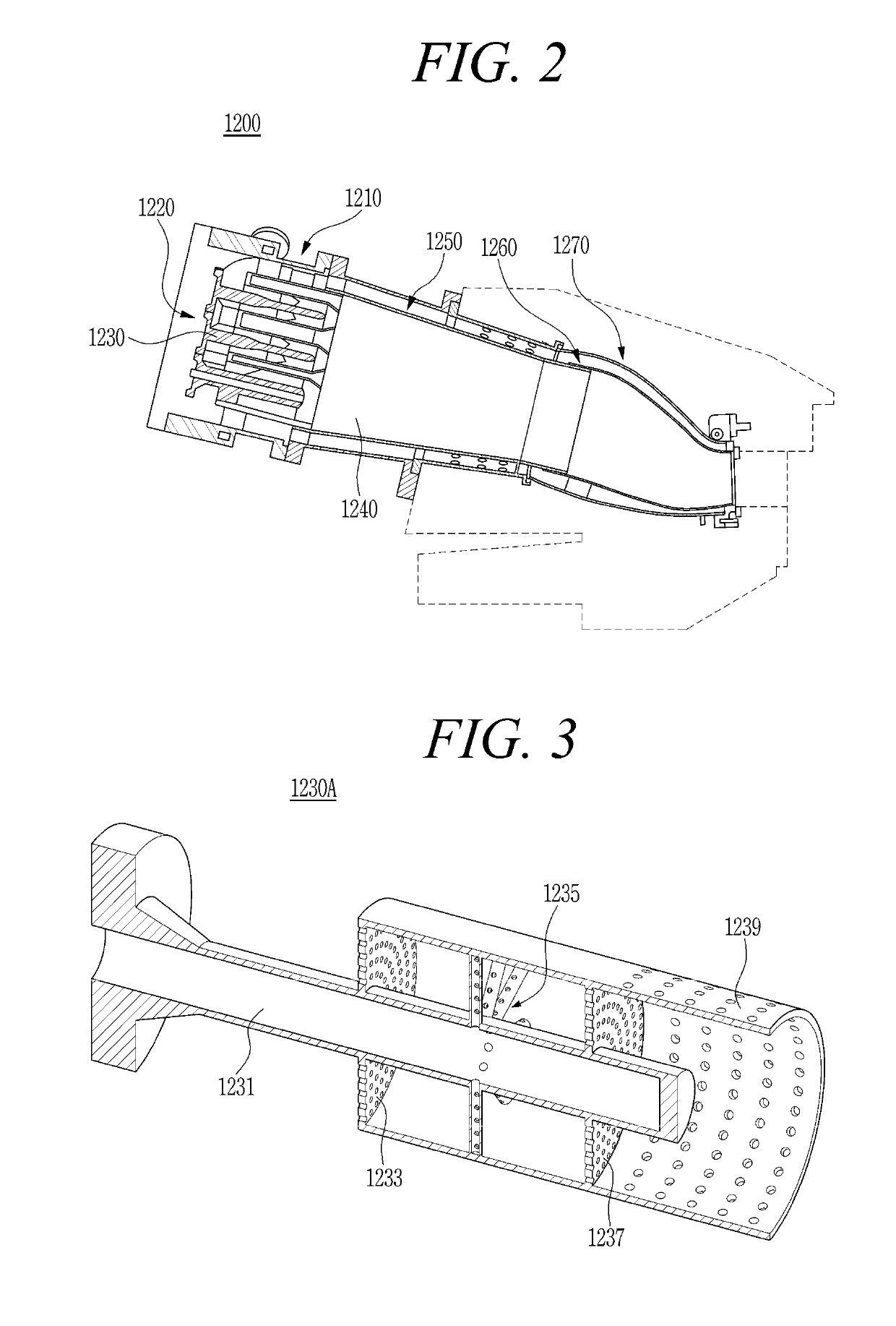
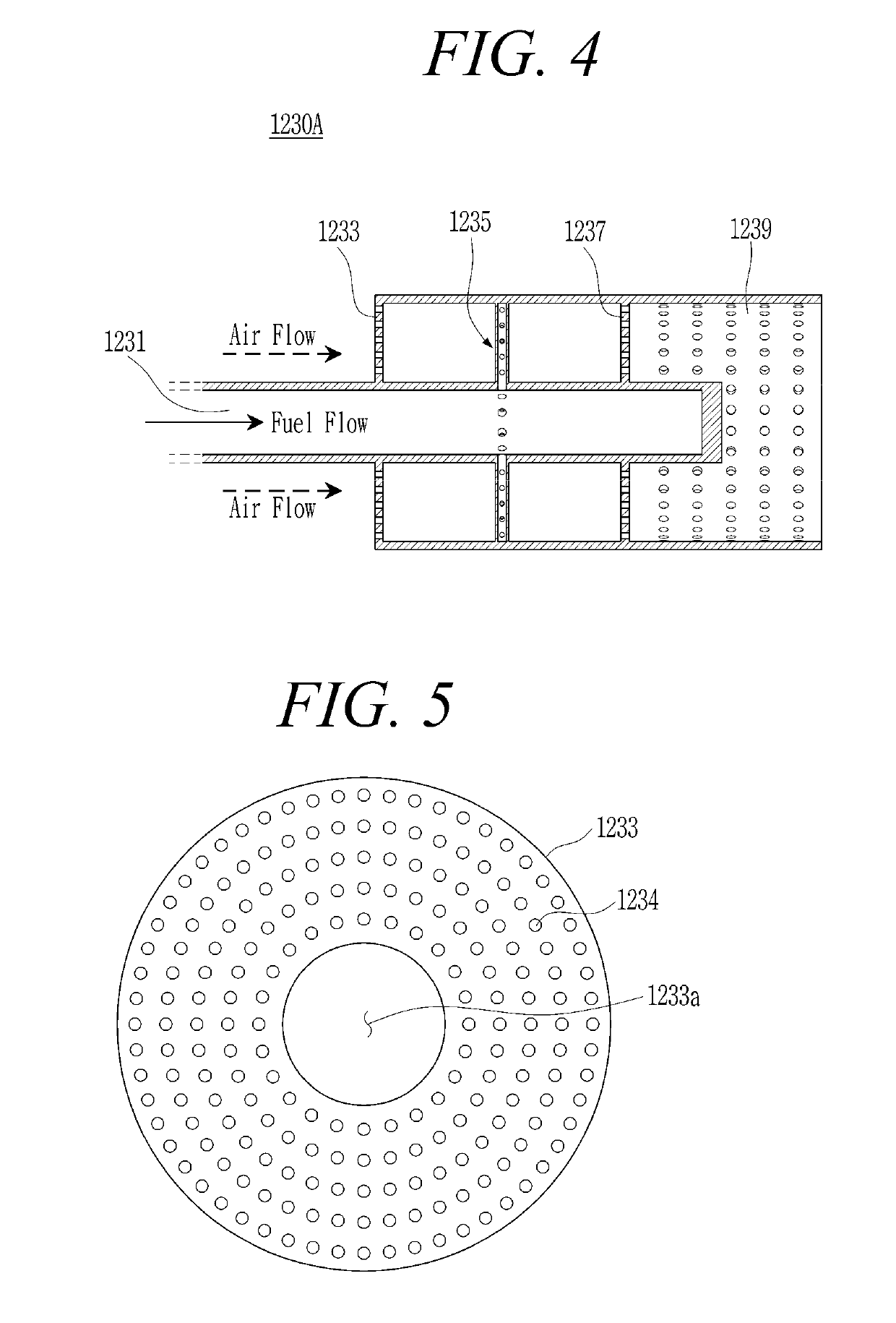
[0045]Exemplary embodiments of the present disclosure will be described below in more detail with reference to the accompanying drawings.

[0046]In certain embodiments, detailed descriptions of configurations well known by those skilled in the art will be omitted to avoid obscuring appreciation of the disclosure. Regarding the reference numerals assigned to the elements in the drawings, it should be noted that the same elements will be specified by the same reference numerals, wherever possible, even though they are illustrated in different drawings. It should be considered that the thickness of each line or the size of each component in the drawings may be exaggeratedly illustrated for clarity and convenience of description.

[0047]In addition, terms such as “first”, “second”, “A”, “B”, “(a)”, and “(b)” may be used herein to describe components in the embodiments of the present disclosure. These terms are not used to define an essence, order or sequence of a corresponding component but...


PUM


Abstract

The present disclosure relates to a fuel supply device for gas turbines, and a fuel nozzle and gas turbine having the same. The fuel supply device of present disclosure is mounted to the fuel nozzle for a uniform flow of air introduced thereinto and for allowing uniform mixing with fuel. The present disclosure allows a uniform fuel-air mixture to be supplied to a combustion chamber. According to the present disclosure, it is possible to uniformly supply a fuel-air mixture to a combustion chamber by arranging a plurality of perforated plates in a fuel supply device for gas turbines, to suppress generation of nitrogen oxides, and to prevent flame from stagnating or flowing backward.

Description

CROSS-REFERENCE TO RELATED APPLICATION[0001]This application claims priority to Korean Patent Application No. 10-2018-0030676, filed on Mar. 16, 2018, the disclosure of which is incorporated herein by reference in its entirety.BACKGROUND OF THE DISCLOSUREField of the Disclosure[0002]Exemplary embodiments of the present disclosure relate to a fuel supply device for gas turbines, and a fuel nozzle and gas turbine having the same.Description of the Related Art[0003]Turbines are machines that obtain rotational force by impulsive or reaction force using the flow of a compressible fluid such as steam or gas, and include a steam turbine using steam, a gas turbine using hot combustion gas, and so on.[0004]Among them, the gas turbine largely includes a compressor, a combustor, and a turbine. The compressor is provided with an air inlet for introduction of air, and includes a plurality of compressor vanes and compressor blades alternately arranged in a compressor casing.[0005]The combustor su...

Claims


Application Information

Patent Timeline
Patent Type & Authority Applications(United States)
IPC IPC(8): F23R3/28
CPCF23R3/286F23R3/26F02C7/22F05D2240/35F23R3/16
Inventor CHOI, INCHANHAN, DONGSIK
Owner DOOSAN HEAVY IND & CONSTR CO LTD
Learn More