
Light emitting device

a technology of light emitting device and light source, which is applied in the direction of semiconductor devices, lighting and heating apparatus, instruments, etc., can solve the problems of increasing manufacturing costs, increasing the number of components, and complicated devices, and achieves improved luminance uniformity, reduced number of luminous elements, and thin configuration

Inactive Publication Date: 2014-12-30
SAMSUNG ELECTRONICS CO LTD
View PDF9 Cites 18 Cited by
  • Summary
  • Abstract
  • Description
  • Claims
  • Application Information

AI Technical Summary

Benefits of technology

This patent is for a lighting device that has better uniformity and uses fewer light sources, making it thinner and more efficient than existing devices.

Problems solved by technology

However, an increase in the number of luminous elements may disadvantageously result in an increase in manufacturing costs, and a unit for dissipating heat generated from a large number of luminous elements is required, increasing the number of components and leading to the device being complicated.

Method used


Image

  • Light emitting device
  • Light emitting device
  • Light emitting device

Examples


Embodiment Construction

[0032]Exemplary embodiments of the present disclosure will now be described in detail with reference to the accompanying drawings.

[0033]The exemplary embodiments may, however, be embodied in many different forms and should not be construed as being limited to the exemplary embodiments set forth herein.

[0034]Rather, these exemplary embodiments are provided so that this disclosure will be thorough and complete, and will fully convey the scope of the disclosure to those skilled in the art.

[0035]In the drawings, the shapes and dimensions of elements may be exaggerated for clarity, and the same reference numerals will be used throughout to designate the same or like components.

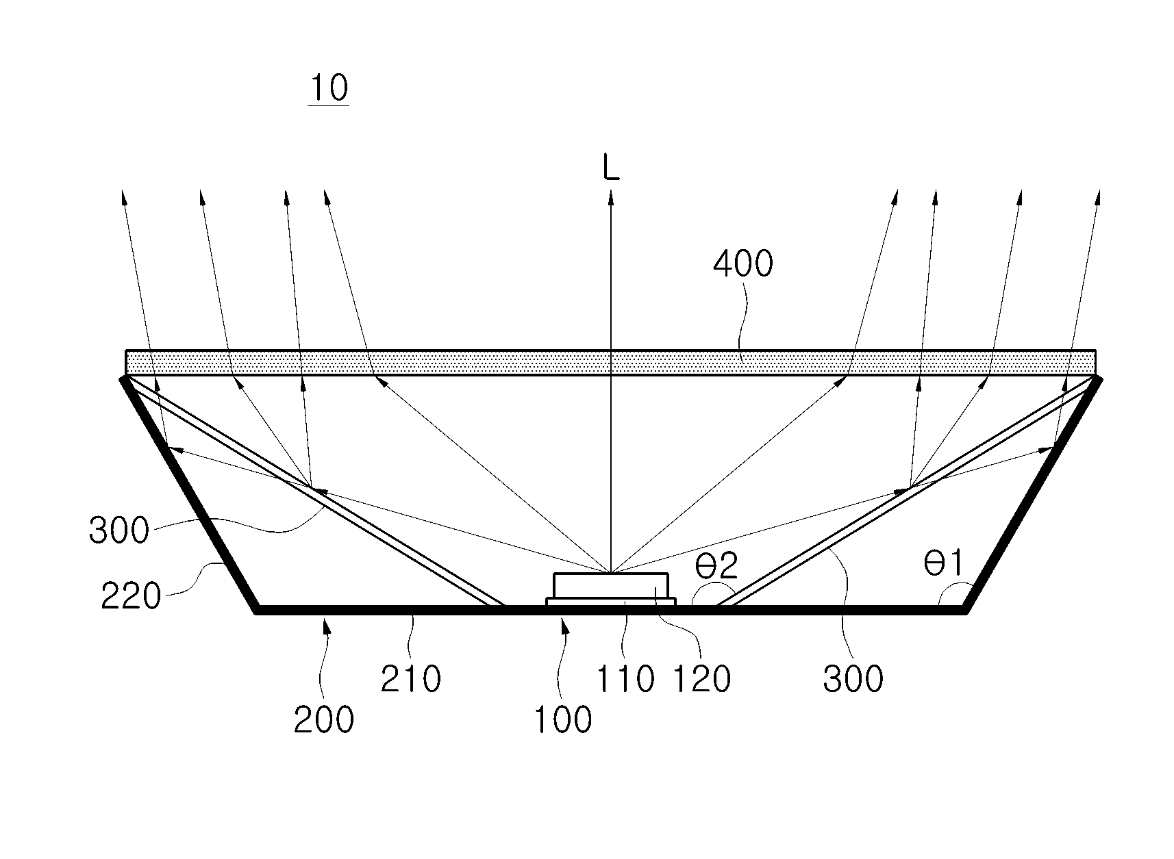
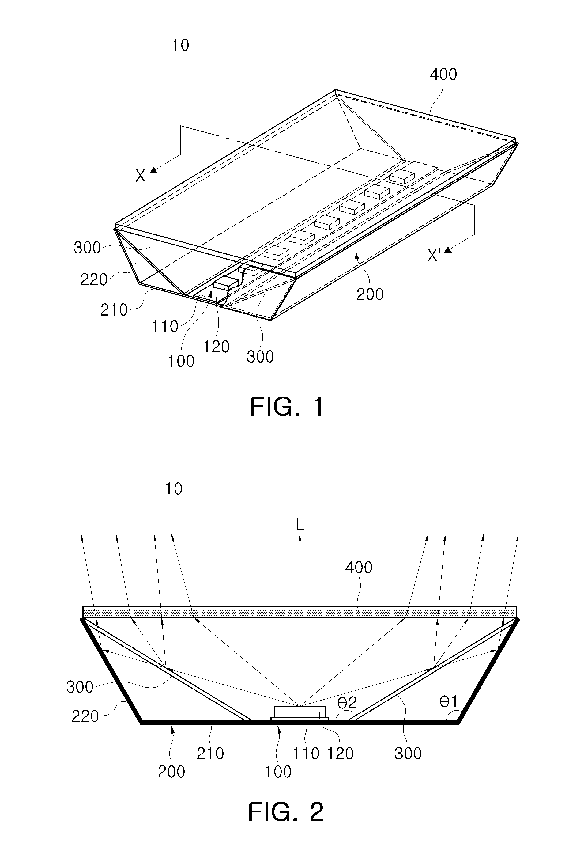
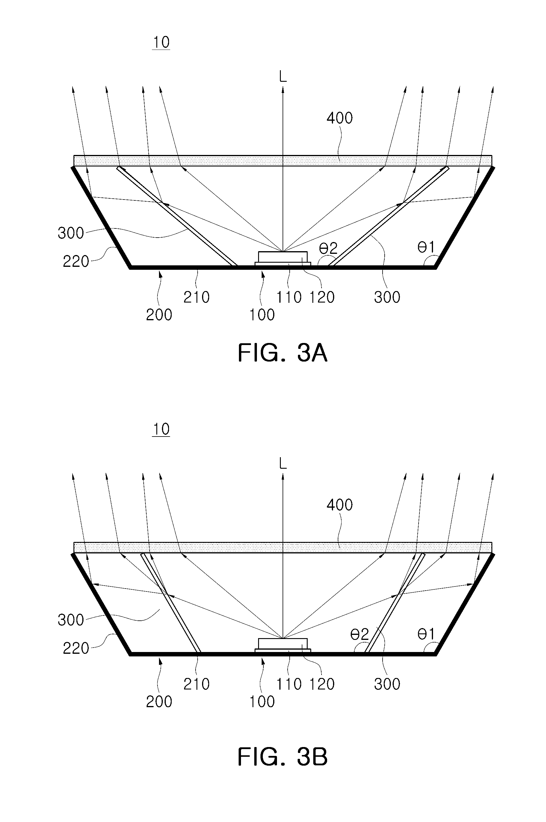
[0036]A light emitting device 10 according to an exemplary embodiment of the present disclosure will be described with reference to FIGS. 1 through 4. FIG. 1 is a perspective view schematically illustrating a light emitting device according to an exemplary embodiment. FIG. 2 is a cross-sectional view of the light e...


PUM

PropertyMeasurementUnit
perimeteraaaaaaaaaa
areaaaaaaaaaaa
luminanceaaaaaaaaaa

Abstract

A light emitting device includes: a light source that emits light; a reflective unit disposed around a perimeter of the light source and having a reflective surface; and a diffusion unit that is disposed between the light source and the reflective surface and is configured to reflect a partial amount of the light emitted from the light source and transmit another partial amount of the light emitted from the light source toward the reflective surface.

Description

CROSS-REFERENCE TO RELATED APPLICATIONS[0001]This application claims the priority of Korean Patent Application No. 10-2012-0044964 filed on Apr. 27, 2012, in the Korean Intellectual Property Office, the disclosure of which is incorporated herein by reference in its entirety.BACKGROUND[0002]1. Field[0003]The present disclosure relates to a light emitting device.[0004]2. Description of the Related Art[0005]A light emitting device configured as a light emitting diode (LED), which emits light according to an electrical signal applied thereto, is widely used as a light emitting source in various electronic products as well as in mobile communications terminals such as mobile phones, personal digital assistants (PDAs), and the like.[0006]In the case of an image display device such as a liquid crystal display (LCD) or the like, a backlight unit for illumination from the rear of a liquid crystal panel is used as a surface light emitting device in order to illuminate the liquid crystal panel...

Claims


Application Information

Patent Timeline
Patent Type & Authority Patents(United States)
IPC IPC(8): F21V7/00F21V13/02F21V5/00
CPCF21V3/04F21V13/02F21V7/0016F21Y2101/02G02F1/133611F21V13/10G02F1/133606F21V7/22F21V7/0033F21V7/005F21V29/2206F21V29/74F21Y2115/10F21V7/28F21V7/26H01L33/48H01L33/60
Inventor PARK, JONG, JIN
Owner SAMSUNG ELECTRONICS CO LTD
Learn More