Suspension substrate, suspension, head suspension, and hard disk drive

a technology of suspension substrate and head suspension, which is applied in the direction of electrical apparatus construction details, instruments, record information storage, etc., can solve the problems of small gap provided between the piezoelectric element and the liquid stopper, large amount of conductive adhesive may be overflowing outward, and short circuit between the electrodes of the piezoelectric elemen

Active Publication Date: 2014-12-30
DAI NIPPON PRINTING CO LTD
View PDF10 Cites 11 Cited by
  • Summary
  • Abstract
  • Description
  • Claims
  • Application Information

AI Technical Summary

Benefits of technology

[0009]The present invention was made in light of the above problem. Therefore, it is an object of this invention to provide the suspension substrate, suspension, head suspension and hard disk drive, respectively capable of preventing the short circuit between the electrodes of each actuator element connected with the suspension substrate via the conductive adhesive.
[0022]Therefore, according to the present invention, the outer periphery of the metallic support layer can be visually confirmed when the actuator element is connected with the connection structure region of the suspension substrate via the conductive adhesive. This visual confirmation ability relative to the outer periphery of the metallic support layer can effectively prevent the conductive adhesive from being unduly overflowed from the metallic support layer and thus reaching any other metallic structure located around the connection structure region. Therefore, the short circuit between the electrodes of the actuator element can be securely prevented.

Problems solved by technology

However, there is a small gap provided between the piezoelectric element and the liquid stopper.
Therefore, depending on the amount of the injected conductive adhesive, a large amount of the conductive adhesive may be overflowed outward from the liquid stopper.
In this case, if the terminal part is located in the vicinity of a load beam welded to the base plate, the conductive adhesive overflowed from the liquid stopper may reach the load beam, resulting in the short circuit between the electrodes of the piezoelectric element.

Method used


Image

  • Suspension substrate, suspension, head suspension, and hard disk drive
  • Suspension substrate, suspension, head suspension, and hard disk drive
  • Suspension substrate, suspension, head suspension, and hard disk drive

Examples


first embodiment

[0034]Now referring to FIGS. 1 through 10, the suspension substrate, suspension, head suspension and hard disk drive, respectively related to the first embodiment of the present invention, will be described.

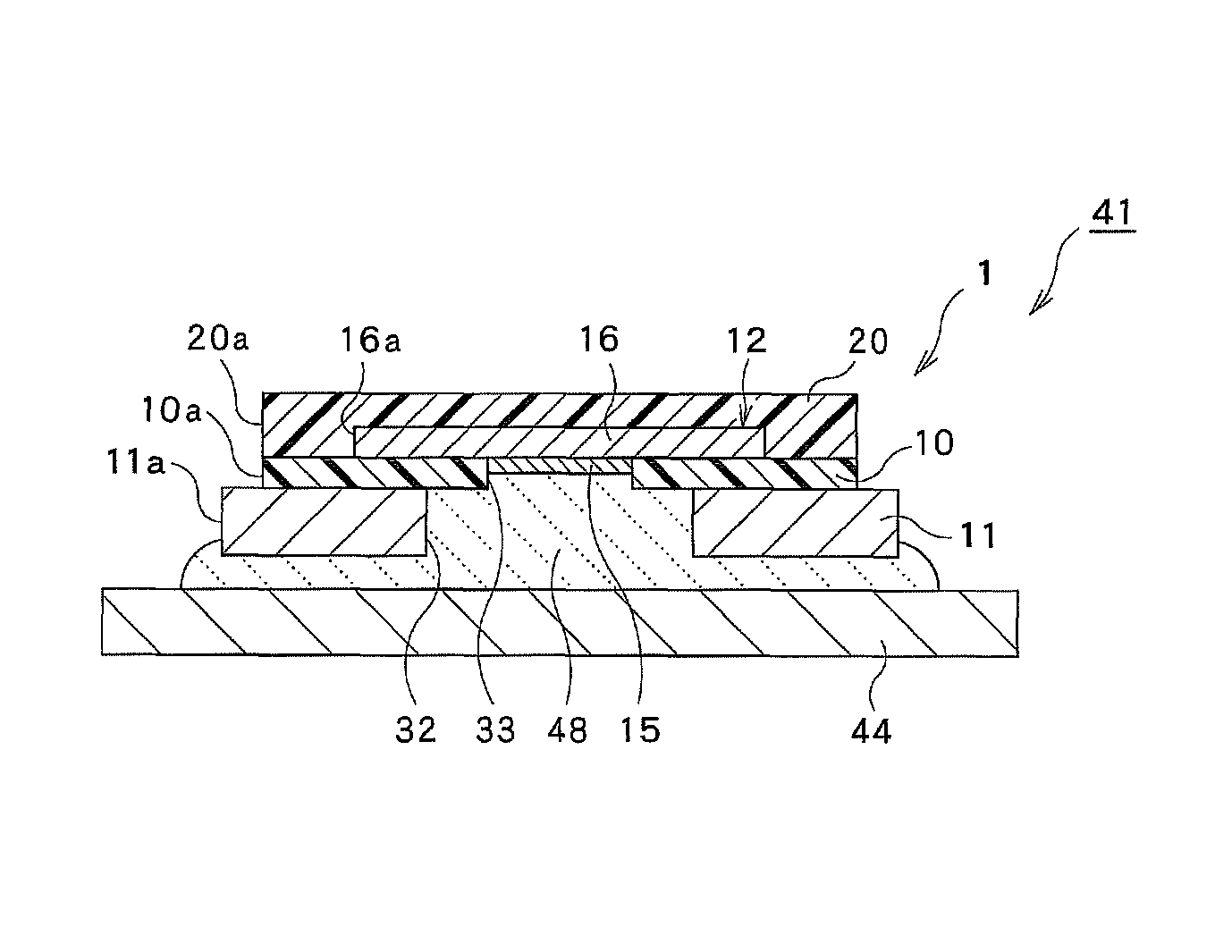
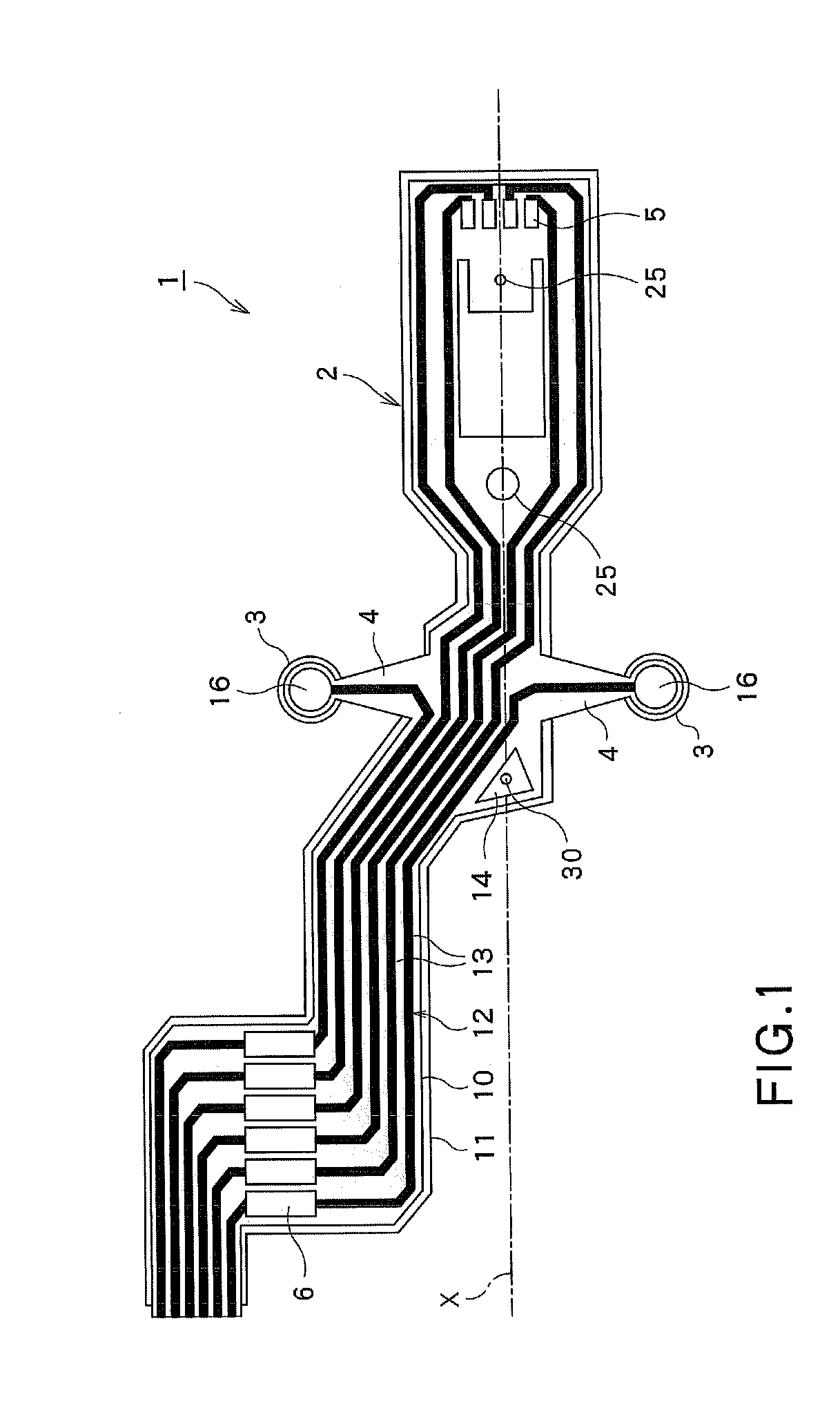
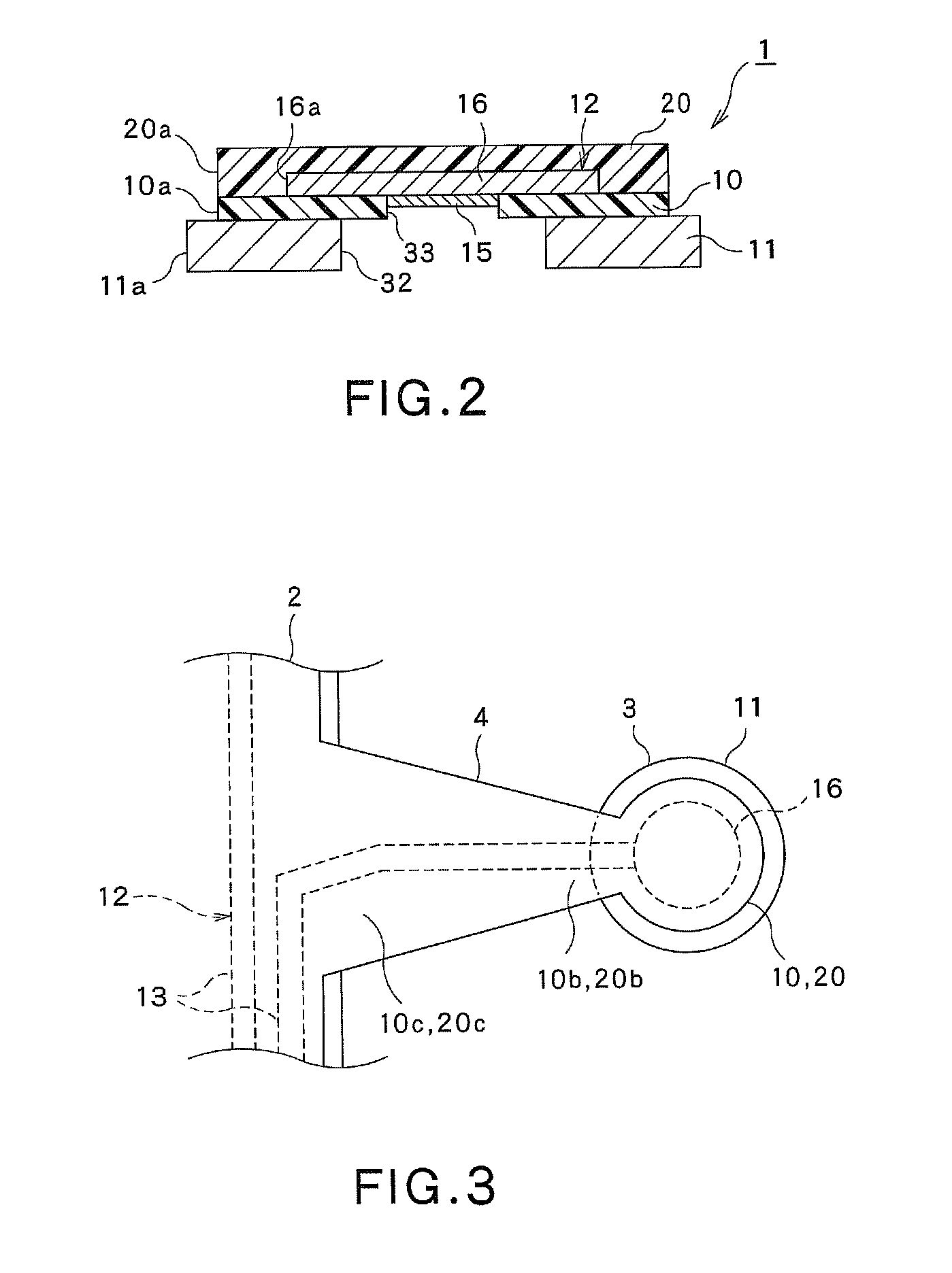
[0035]As shown in FIG. 1, the suspension substrate 1 includes the substrate main body region 2, a pair of connection structure regions 3, respectively connectable with the piezoelectric elements 44 (i.e., the actuator elements, respectively shown in FIG. 4) that will be respectively located on both sides of the substrate main body region 2, and a pair of extension structure regions 4, respectively extending between the substrate main body region 2 and each connection structure region 3. It is noted that the piezoelectric elements 44 will be described later. In the substrate main body region 2, a head terminal 5 provided to be connected with a slider 52 (as is shown in FIG. 8 and will be described later), and an external equipment connection terminal 6 adapted to be connected with...

second embodiment

[0088]Now, referring to FIG. 11, the suspension substrate, suspension, head suspension and hard disk drive, respectively related to the second embodiment of the present invention, will be described.

[0089]A key point of this second embodiment shown in FIG. 11 is that a through hole for exposing the wiring connection section of the wiring layer is provided to extend through the protective layer, wherein the gold plating is provided to the exposed portion of the wiring connection section in the though hole. Namely, except for this key point, the other construction of the second embodiment is substantially the same as the first embodiment shown in FIGS. 1 through 10. It is noted that like parts in the first embodiment shown in FIGS. 1 through 10 are respectively designated by like reference numerals in FIG. 11, and further explanation on such parts will be omitted below.

[0090]Namely, in each connection structure region 3 of the suspension substrate 1, as shown in FIG. 11, an inspection ...


PUM


Abstract

A suspension substrate according to the present invention includes an insulating layer and a metallic support layer provided on the actuator element's side of the insulating layer. On the other side of the insulating layer, a wiring layer is provided. This wiring layer includes a plurality of wirings and a wiring connection section that can be electrically connected with the actuator element via a conductive adhesive. The outer periphery of the metallic support layer in a connection structure region is positioned outside relative to the outer periphery of the insulating layer and the outer periphery of the wiring connection section of the wiring layer.

Description

CROSS REFERENCE TO RELATED APPLICATIONS[0001]This application is based on the prior Japanese Patent Application No. 2010-154135 filed on Jul. 6, 2010, the entire contents of which are incorporated herein by reference.FIELD OF THE INVENTION[0002]The present invention relates to a suspension substrate, a suspension, a head suspension and a hard disk drive. In particular, this invention relates to the suspension substrate, suspension, head suspension and hard disk drive, respectively adapted for preventing a short circuit between electrodes of each actuator element connected with the suspension substrate via a conductive adhesive.BACKGROUND ART[0003]Generally, the hard disk drive (HDD) includes the suspension substrate on which a magnetic head slider mounted. In this case, the magnetic head slider is provided for writing and reading data relative to a disk adapted for storing therein the data. The suspension substrate includes a metallic support layer and a wiring layer layered on the ...

Claims


Application Information

Patent Timeline
Patent Type & Authority Patents(United States)
IPC IPC(8): H05K3/32H05K1/05H05K1/11
CPCH05K2201/10083H05K3/321H05K2201/0397H05K1/05
Inventor OHNUKI, MASAO
Owner DAI NIPPON PRINTING CO LTD
Why Eureka
Try Eureka