
Light beam scanning device that performs high-accuracy light amount control, method of controlling the device, storage medium, and image forming apparatus

a scanning device and high-accuracy technology, applied in the direction of electrographic process equipment, instruments, printing, etc., can solve the problems of large correction error, difficult to know the characteristics of laser diodes alone, and lowered accuracy of light amount control, so as to achieve the effect of not making the control complicated

Inactive Publication Date: 2014-12-30
CANON KK
View PDF8 Cites 1 Cited by
  • Summary
  • Abstract
  • Description
  • Claims
  • Application Information

AI Technical Summary

Benefits of technology

The present invention offers a light beam scanning device that can manage light amounts accurately without becoming complicated when using laser diodes that emit light in a non-linear way.

Problems solved by technology

Therefore, the method of storing I-L characteristics in a manner associated with temperature and performing the light amount control based on the stored I-L characteristics suffers from a problem that a change in the I-L characteristics caused by aging cannot be followed up, whereby the accuracy of the light amount control is lowered as aging advances.
Further, in the case of the method in which the photosensitive drum is irradiated using a plurality of light amounts, and the I-L characteristics of the laser diode are predicted and corrected based on the surface potentials of the photosensitive drum, it is difficult to know the characteristics of the laser diode alone because the control becomes complicated the photosensitive drum has a characteristic that the relationship between the amount of change in the surface potential and the amount of exposure is not linear, and so forth.
This brings about the problem that when the optical correction of the light beam scanning device is performed, there occurs a large correction error.

Method used


Image

  • Light beam scanning device that performs high-accuracy light amount control, method of controlling the device, storage medium, and image forming apparatus
  • Light beam scanning device that performs high-accuracy light amount control, method of controlling the device, storage medium, and image forming apparatus
  • Light beam scanning device that performs high-accuracy light amount control, method of controlling the device, storage medium, and image forming apparatus

Examples


Embodiment Construction

[0036]The present invention will now be described in detail below with reference to the accompanying drawings showing embodiments thereof.

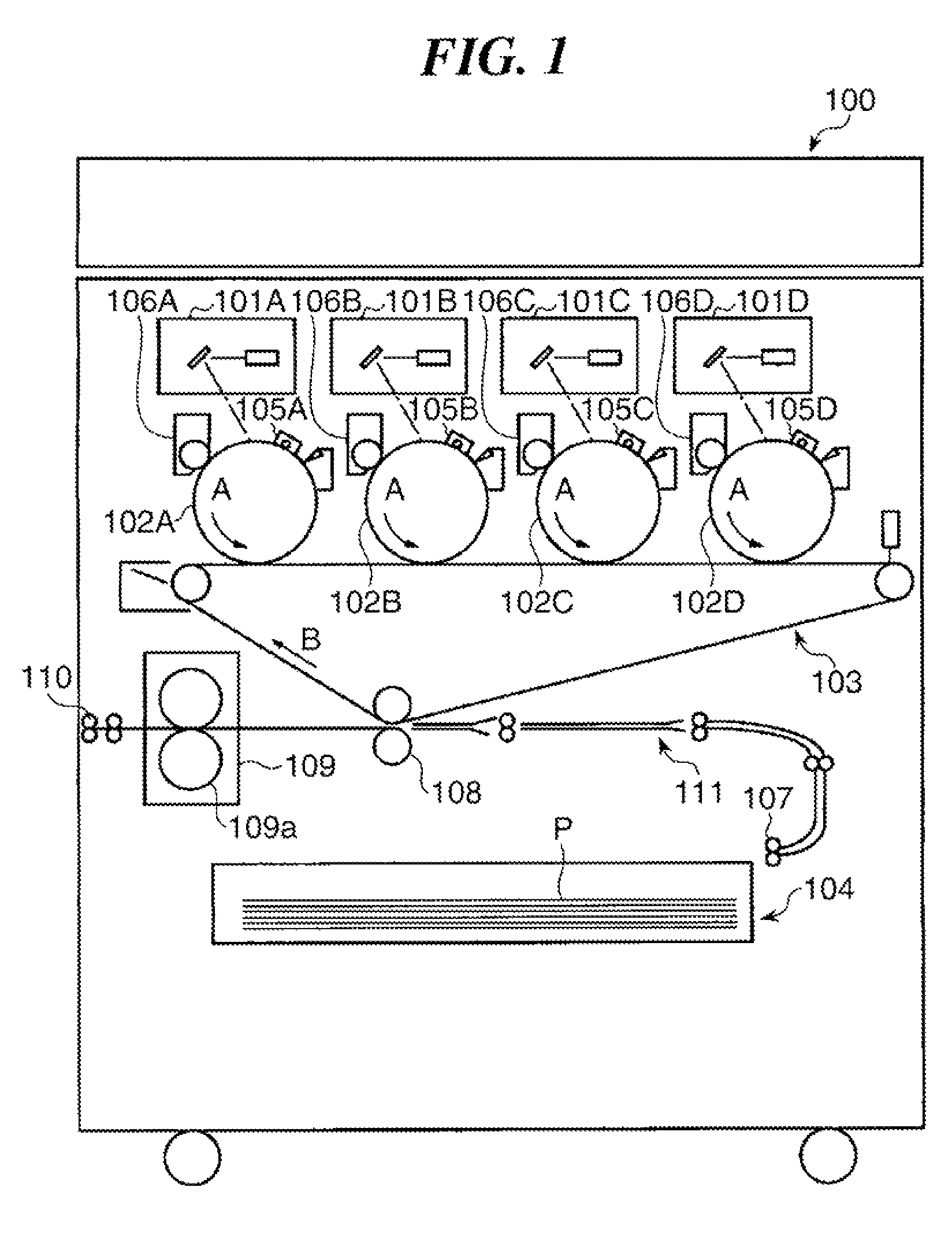
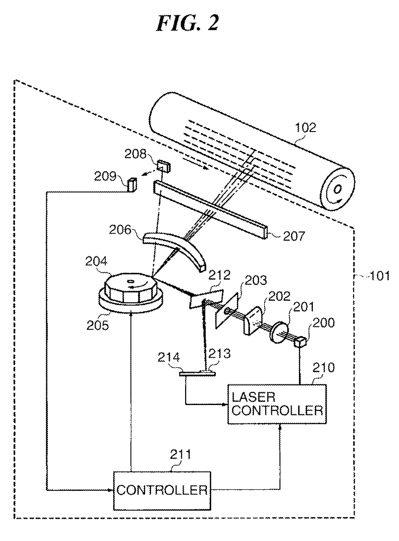
[0037]FIG. 1 is a cross-sectional view of the overall arrangement of an image forming apparatus according to an embodiment of the present invention. The image forming apparatus comprises a plurality of image forming units each equipped with a light beam scanning device (hereinafter referred to as the “laser scanner”).

[0038]Referring to FIG. 1, an electrophotographic color copying machine 100 as the image forming apparatus mainly comprises the image forming units, an intermediate transfer unit 103, a conveying unit 111, and a sheet feeder unit 104, which are sequentially arranged below the image forming apparatus, as viewed in FIG. 1. The plurality of e.g. four image forming units include photosensitive drums 102A to 102D as photosensitive members, primary electrostatic chargers 105A to 105D, developing devices 106A to 106D, and the laser scanners ...


PUM


Abstract

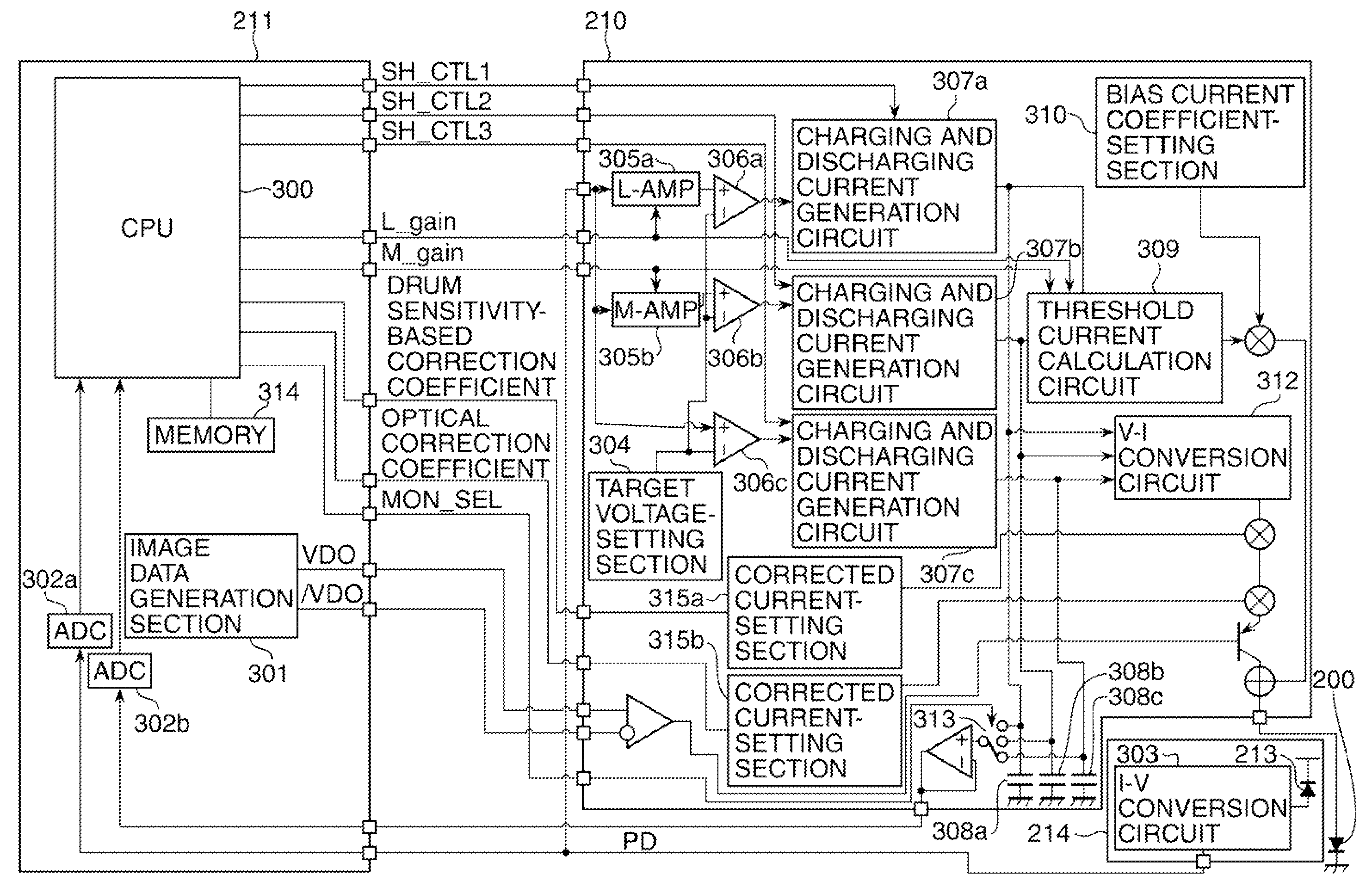
A light beam scanning device which is capable of performing high-accuracy light amount control without complicated control even when the device includes a laser diode having non-linear I-L characteristics. Gain circuits set the amount of light to be emitted from the laser diode. A PD circuit board detects the amount of the emitted light. A laser controller controls the amount of the emitted light by adjusting drive current applied to the laser diode based on a detection output from the PD circuit board. A CPU corrects data for correcting the drive current. The CPU decides a light amount correction range for correcting the light amount based on the correction data, calculates the slope of the I-L characteristics in the light amount correction range based on light amounts at two points within the light amount correction range and drive currents associated with the respective light amounts, and corrects the correction data using the calculated slope.

Description

BACKGROUND OF THE INVENTION[0001]1. Field of the Invention[0002]The present invention relates to a light beam scanning device having nonlinear drive current-light amount characteristics (I-L characteristics), a method of controlling the same, a storage medium, and an image forming apparatus including the light beam scanning device.[0003]2. Description of the Related Art[0004]It is known that in a general semiconductor laser diode used in an image forming apparatus and the like, the slope of light emission characteristics representative of a correspondence relationship between drive current and light amount (hereinafter referred to as the “I-L characteristics”) is non-linear, as shown in FIG. 17. Further, in such a laser diode, there has been proposed the following control technique for controlling a target light amount: A threshold current Ith of the laser diode and a slope η of the I-L characteristics are calculated based on light amounts (P1 and P2) at two points and drive current...

Claims


Application Information

Patent Timeline
Patent Type & Authority Patents(United States)
IPC IPC(8): G03G15/043B41J2/385B41J2/435
CPCG03G2215/0129G03G15/043
Inventor AKAGI, DAISUKE
Owner CANON KK
Learn More