Centrifugal pendulum mechanism

a centrifugal pendulum and pendulum technology, applied in mechanical equipment, vibration suppression adjustment, springs/dampers, etc., can solve the problem of high improbability of edge-to-edge contact, and achieve the effect of improving the noise quality of centrifugal pendulum devices

Inactive Publication Date: 2015-01-06
SCHAEFFLER TECH AG & CO KG
View PDF15 Cites 7 Cited by
  • Summary
  • Abstract
  • Description
  • Claims
  • Application Information

AI Technical Summary

Benefits of technology

[0005]The object of the invention is to improve the noise quality of a centrifugal pendulum device while optimally utilizing the installation space, preferably by damping or avoiding the impact between circumferentially adjacent pendulum masses.
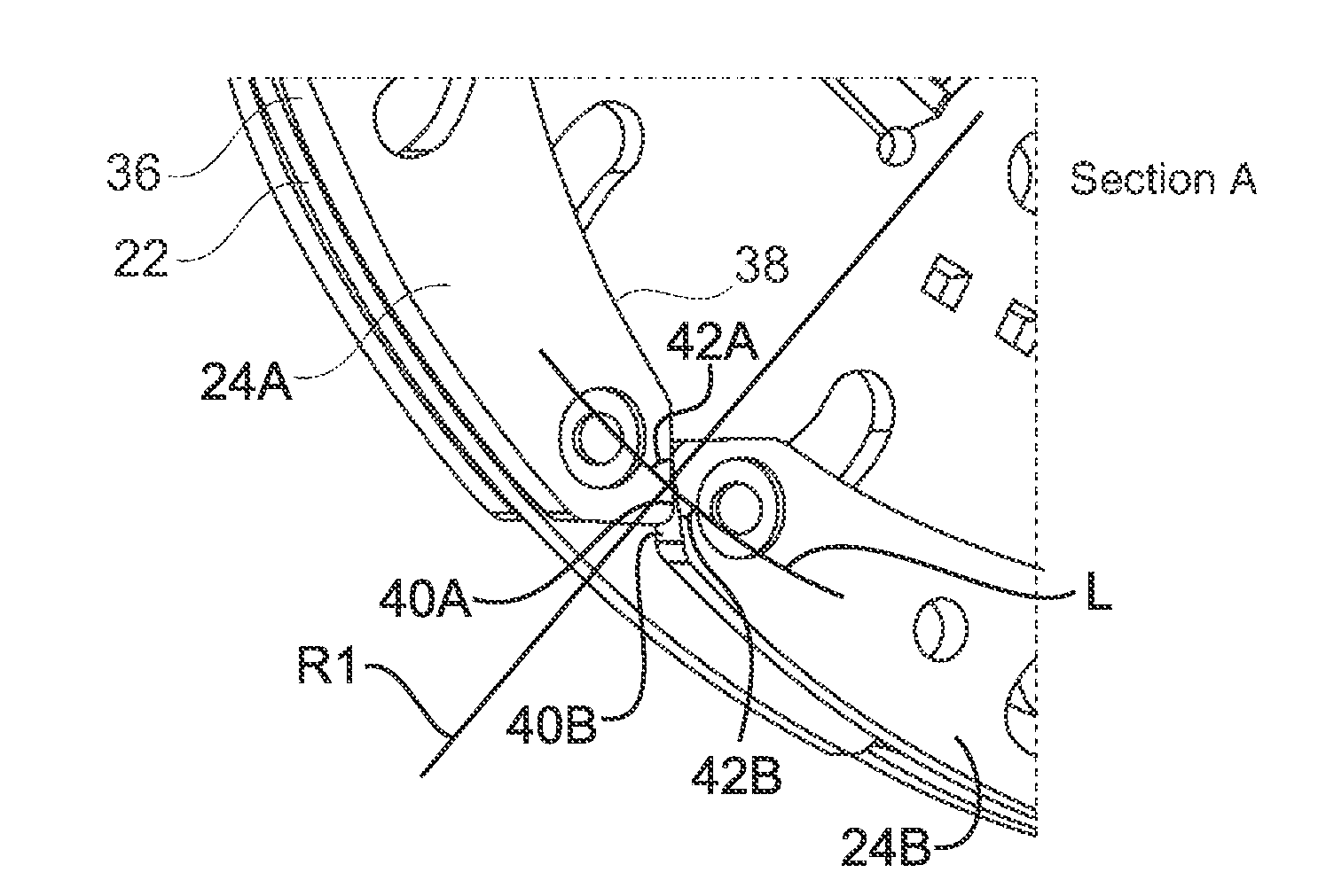
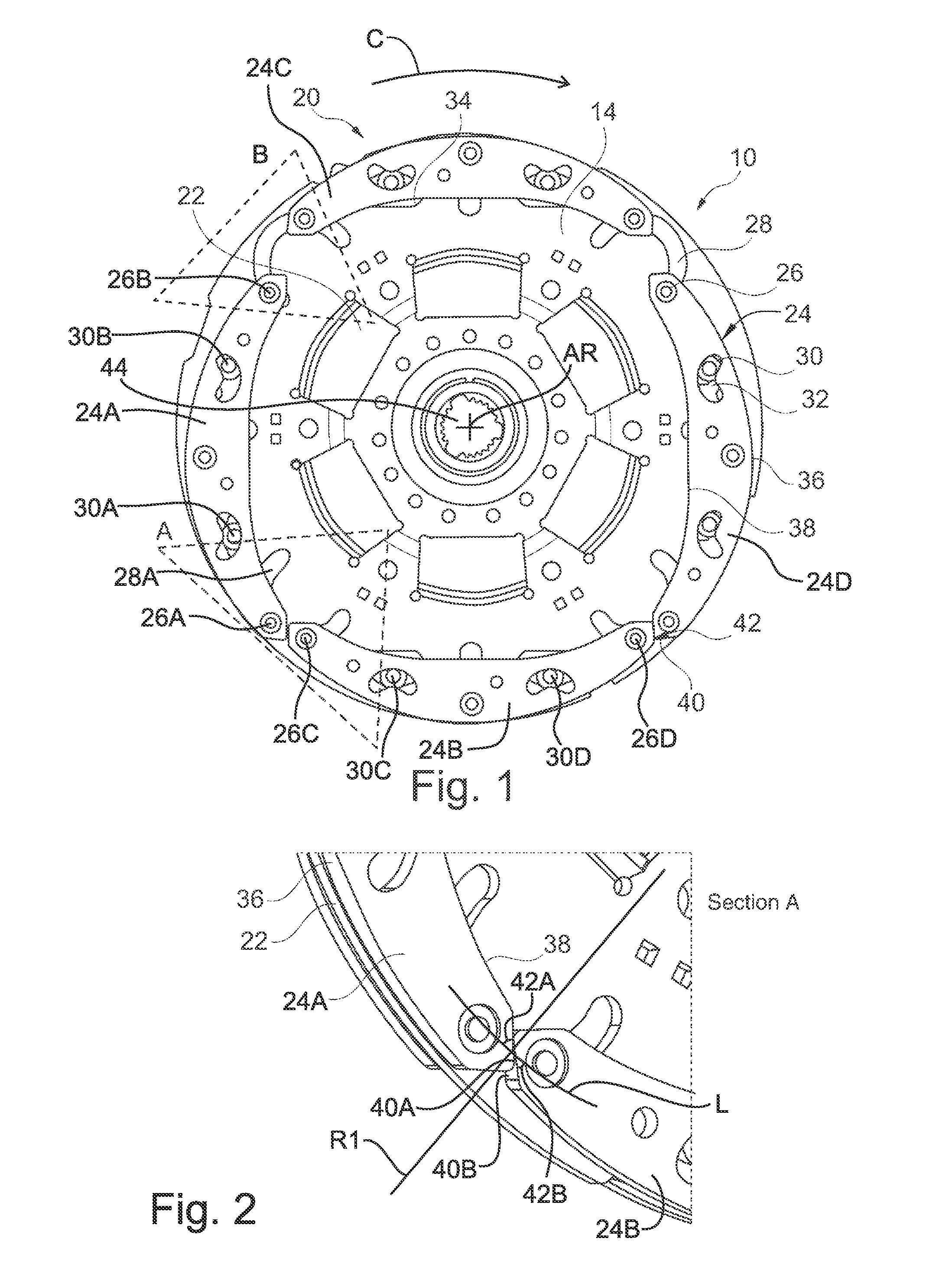
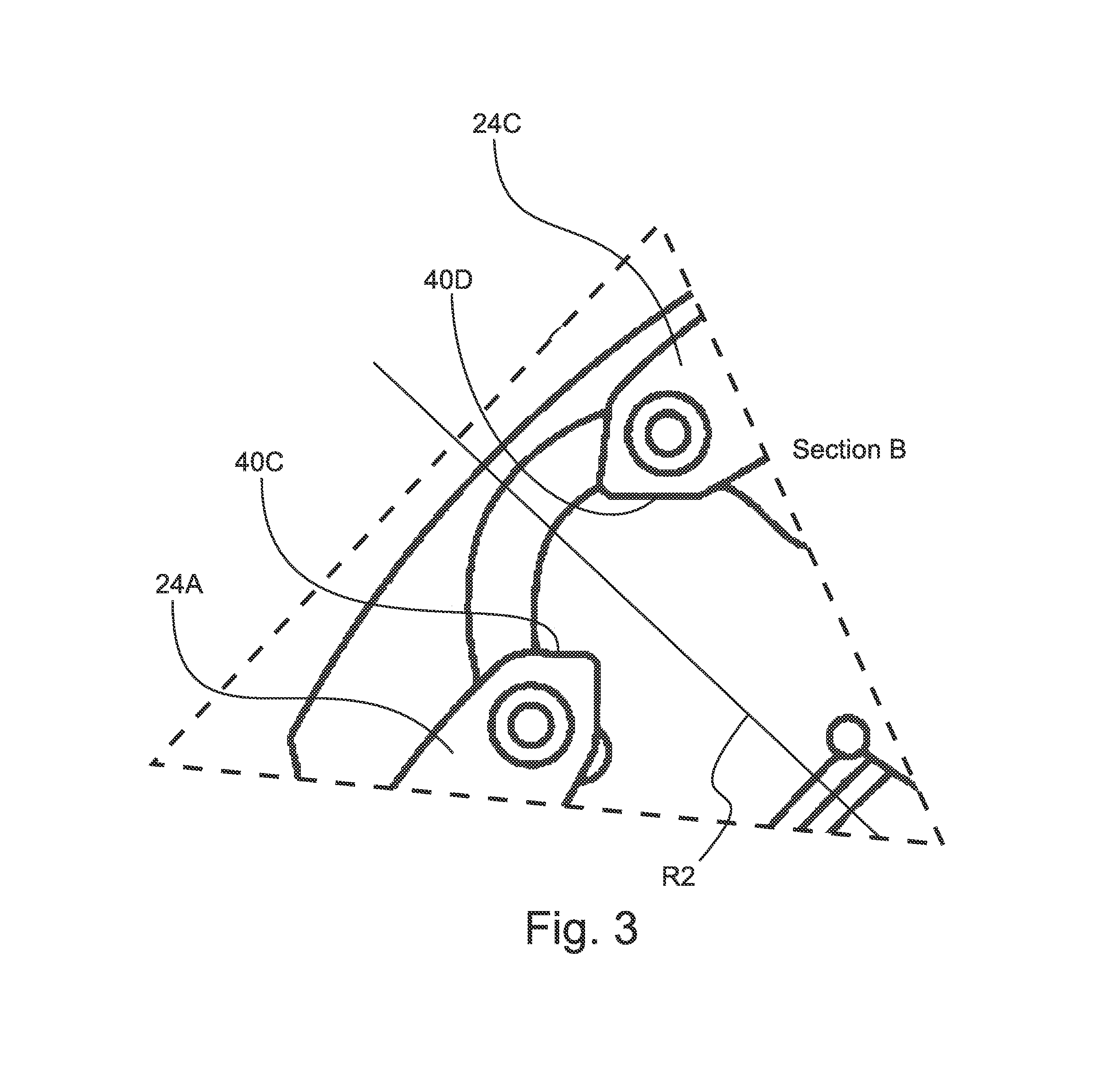
[0006]Accordingly, a centrifugal pendulum mechanism is proposed having a pendulum flange and pendulum masses, which are fastened by means of bolts on both sides of the pendulum flange and are guided by means of rollers and can be pivoted slightly relative to the pendulum flange, where at least two pendulum masses are arranged on the pendulum flange so as to be circumferentially adjacent, and one pendulum mass has a lateral surface that faces the adjacent pendulum mass, and the contour of the lateral surface is at a substantially acute angle. When the pendulum masses contact each other while the pendulum flange is rotating and / or when the pendulum flange transitions from rotating to stationary, this can cause one pendulum mass to smoothly glide off the circumferentially adjacent pendulum mass. The contour of the lateral surface can be designed such that two neighboring pendulum masses can execute a very expansive pendulum movement relative to the pendulum flange while the centrifugal pendulum mechanism is operating and not contact the pendulum masses.
[0007]In one embodiment of the invention, the contours of two facing lateral surfaces of adjacent pendulum masses are at an acute angle. The contour of the lateral surface of a pendulum mass is preferably designed to symmetrically mirror the contour of the neighboring lateral surface of the adjacent pendulum mass with reference to a radial line. The edge of the contour can be rounded if two adjacent pendulum masses first contact each other with the edge under certain circumstances. However, the contour can be designed so that edge-to-edge contact is highly improbable.

Problems solved by technology

However, the contour can be designed so that edge-to-edge contact is highly improbable.

Method used


Image

  • Centrifugal pendulum mechanism
  • Centrifugal pendulum mechanism
  • Centrifugal pendulum mechanism

Examples


Embodiment Construction

[0016]At the outset, it should be appreciated that like drawing numbers on different drawing views identify identical, or functionally similar, structural elements of the invention. While the present invention is described with respect to what is presently considered to be the preferred aspects, it is to be understood that the invention as claimed is not limited to the disclosed aspects.

[0017]Furthermore, it is understood that this invention is not limited to the particular methodology, materials and modifications described and, as such, may, of course, vary. It is also understood that the terminology used herein is for the purpose of describing particular aspects only, and is not intended to limit the scope of the present invention, which is limited only by the appended claims.

[0018]Unless defined otherwise, all technical and scientific terms used herein have the same meaning as commonly understood to one of ordinary skill in the art to which this invention belongs. Although any me...


PUM


Abstract

A centrifugal pendulum mechanism having a pendulum flange and pendulum masses, which are fastened by bolts on both sides of the pendulum flange and are guided by rollers and can be pivoted slightly relative to the pendulum flange. At least two pendulum masses are arranged on the pendulum flange so as to be circumferentially adjacent. One pendulum mass has a lateral surface that faces the adjacent pendulum mass, and the contour of the lateral surface is at a substantially acute angle.

Description

CROSS-REFERENCE TO RELATED APPLICATIONS[0001]This application is filed under 35 U.S.C. §120 and §365(c) as a continuation of International Patent Application PCT / DE2011 / 000172, filed Feb. 21, 2011, which application claims priority from German Patent Application No. 10 2010 011 140.6, filed Mar. 11, 2010, which applications are incorporated herein by reference in their entireties.FIELD OF THE INVENTION[0002]The invention relates to a centrifugal pendulum mechanism.BACKGROUND OF THE INVENTION[0003]Such centrifugal pendulum mechanisms are, for example, known as torsional vibration dampers in terms of their effect, especially when used in drivetrains of motor vehicles, for example, from German Patent Application No. 10 2004 011 830 A1. Pendulum masses are arranged with restricted pivoting on a pendulum flange that is driven by a drive unit, such as an internal combustion engine that is subject to torsional vibrations. A quenching effect of the torsional vibration arises as a result of ...

Claims


Application Information

Patent Timeline
Patent Type & Authority Patents(United States)
IPC IPC(8): F16F15/14
CPCF16F15/145F16F15/14Y10T74/2127Y10T74/2128
Inventor WYSGOL, DARIUSSCHNAEDELBACH, DAVIDKRAUSE, THORSTEN
Owner SCHAEFFLER TECH AG & CO KG
Why Eureka
Try Eureka