Windshield washer fluid heater

a technology of windshield washer and fluid heater, which is applied in the direction of vehicle cleaning, combustion types, lighting and heating apparatus, etc., can solve the problems of inefficient heat transfer between the air and the front windshield, the time required to completely defrost and/or deice the front windshield, and the heat conductance through the windshield and to the ice on the front windshield, etc., and achieves the effect of 15-30 minutes of actual defrost/deice operation

Inactive Publication Date: 2015-01-06
SEEVA TECH INC +1
View PDF120 Cites 9 Cited by
  • Summary
  • Abstract
  • Description
  • Claims
  • Application Information

AI Technical Summary

Benefits of technology

[0015]In operation, the coolant port on each end cap is fluidly connected to the engine coolant system so that the engine coolant flows both around the annular chamber and through the core. Simultaneously, washer fluid flows through the annular chamber in between the core and the subhousing. Consequently, heat from the engine coolant heats the washer fluid as it flows through the annular chamber so that heated washer fluid is sprayed on the front windshield thus deicing and defrosting the front windshield of the vehicle. Since the heat transfer between the heated washer fluid and the ice buildup on the windshield is much more efficient than a hot air system used on the interior of the front windshield, deicing and defogging of the front windshield may be rapidly performed even under severe ice buildup conditions on the windshield.

Problems solved by technology

A primary disadvantage of these previously known warm air windshield defroster systems is that the overall time required to completely defrost and / or deice a front windshield is very lengthy.
First, the engine coolant for the internal combustion engine in the automotive vehicle must become sufficiently heated to heat the air used to defrost the front windshield.
The second, and more important, factor impacting upon the time required to defrost the front windshield using a hot air defrost system is that the heat transfer between the air and the front windshield, as well as the heat conductance through the windshield and to the ice on the front windshield, is very inefficient.
Indeed, in very cold conditions and with substantial ice buildup on the front windshield, the actual defrost / deice operation on the front windshield may require 15-30 minutes.
Such a long time delay to defrost / deice the front windshield not only wastes time, but also engine fuel.
First, both the construction and installation of the electrically heated washer fluid systems are relatively high thus adding a significant cost to the overall vehicle. The automotive industry is particularly competitive so that the addition of a relatively expensive heater system for the washer fluid is economically infeasible.
A second and more significant disadvantage of these previously known electrically heated windshield washer systems is that such systems have been known to malfunction in operation.
Indeed, malfunction of the heater system can result in engine compartment fires and resulting damage to the automotive vehicle.

Method used


Image

  • Windshield washer fluid heater
  • Windshield washer fluid heater
  • Windshield washer fluid heater

Examples


Embodiment Construction

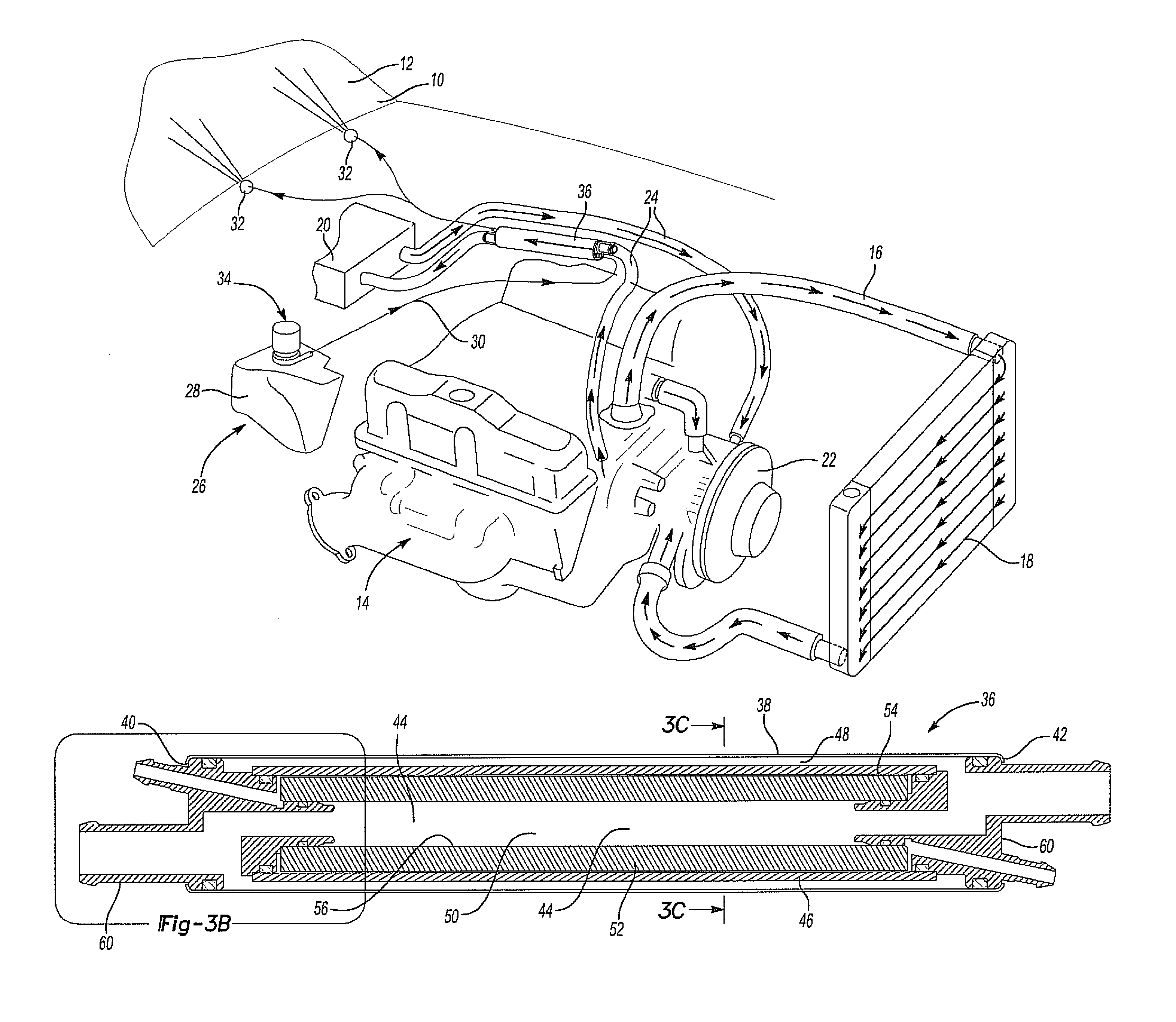
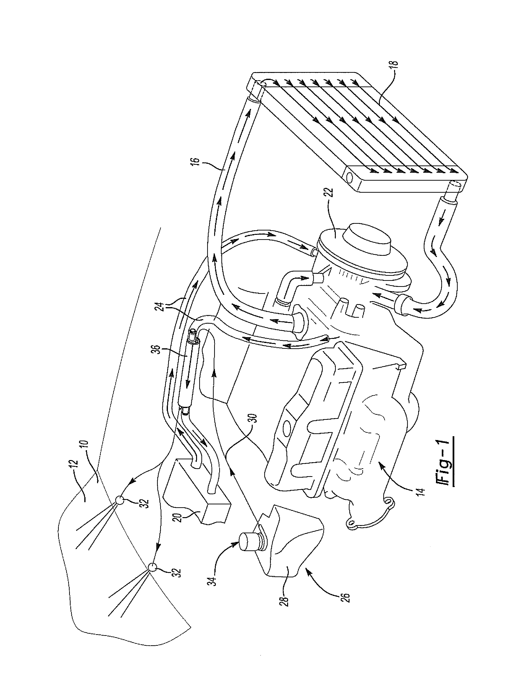
[0025]With reference first to FIG. 1, an automotive vehicle 10 (illustrated only diagrammatically) having a front windshield 12 is shown. The vehicle 10 is powered in part by an internal combustion engine 14 which may be of any conventional construction.

[0026]The engine 14, furthermore, includes an engine coolant system 16. In the conventional fashion, the engine coolant system 16 includes internal cooling passages (not shown) within the engine 14. A radiator 18 cools the liquid coolant contained within the coolant system by airflow through or across the radiator 18. The radiator 18 is fluidly connected to the fluid passageways in the engine 14 by conventional radiator hoses.

[0027]The coolant system 16 further includes a heater core 20 through which the engine coolant is pumped by a coolant pump 22. In the conventional fashion, the heater core 20 is fluidly connected to the engine coolant passageways by heater hoses 24 so that the heat from the core 20 may be used to heat the interi...


PUM


Abstract

A windshield washer fluid heater for an automotive vehicle has an elongated housing with two open ends and in which the housing defines a housing chamber. A tubular subhousing divides the housing chamber into an outer housing chamber and an inner housing chamber. A core is disposed in the inner housing chamber and this core forms an annular chamber between the core and the subhousing. A pair of end caps is attached to the ends of the housing and these end caps sealingly engage the housing and the subchamber to fluidly separate the outer housing chamber from the annular chamber. The housing includes a washer fluid passageway which fluidly connects a washer fluid port on the end cap with the annular chamber as well as a coolant fluid passageway which fluidly connects a coolant port on each end cap with the housing chamber.

Description

CROSS REFERENCE TO RELATED APPLICATIONS[0001]This application is a continuation-in-part of U.S. patent application Ser. No. 12 / 541,207 filed Aug. 14, 2009, which claims priority of U.S. Provisional Patent Application Ser. No. 61 / 089,577 filed Aug. 18, 2008. The contents of both applications are incorporated herein by reference.BACKGROUND OF THE INVENTION[0002]I. Field of the Invention[0003]The present invention relates generally to vehicle windshield defroster systems.[0004]II. Description of Related Art[0005]The defrosting and deicing of automotive vehicles' front windshields has been typically performed by conventional warm air defrosters. These warm air defrosters are heated by the heat from the coolant system which flows through a defroster core. Air fans then circulate air across the core and up to the inside surface of the windshield.[0006]A primary disadvantage of these previously known warm air windshield defroster systems is that the overall time required to completely defr...

Claims


Application Information

Patent Timeline
Patent Type & Authority Patents(United States)
IPC IPC(8): B60S1/46B60H1/00B60S1/38B60S1/48F01P3/12
CPCB60H1/00342B60S1/487F01P3/12B60S2001/3898F28D7/103F28F9/0219F28F9/0253
Inventor LANSINGER, JERETAIT, BRIAN
Owner SEEVA TECH INC
Why Eureka
Try Eureka