
Side light apparatus of chip mounter and light apparatus using the side light apparatus

a technology of side light and mounter, which is applied in the direction of lighting support devices, instruments, image enhancement, etc., can solve the problems of high false defect rate of methods using pneumatic pressure, unstable reference pneumatic pressure, and side lights that cannot be arranged in a row or a circular shap

Active Publication Date: 2015-01-06
HANWHA AEROSPACE CO LTD
View PDF20 Cites 0 Cited by
  • Summary
  • Abstract
  • Description
  • Claims
  • Application Information

AI Technical Summary

Benefits of technology

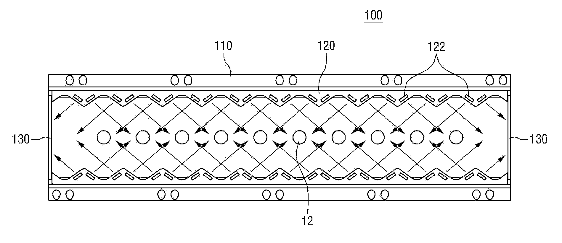
[0019]One or more exemplary embodiments also provide a light apparatus of a chip mounter which can recognize edges of parts and obtain image information of balls of each part accurately since emitted light is reflected by a pair of mirrors installed at both ends of the light apparatus to enter outermost ones of parts picked by spindles of the chip mounter.

Problems solved by technology

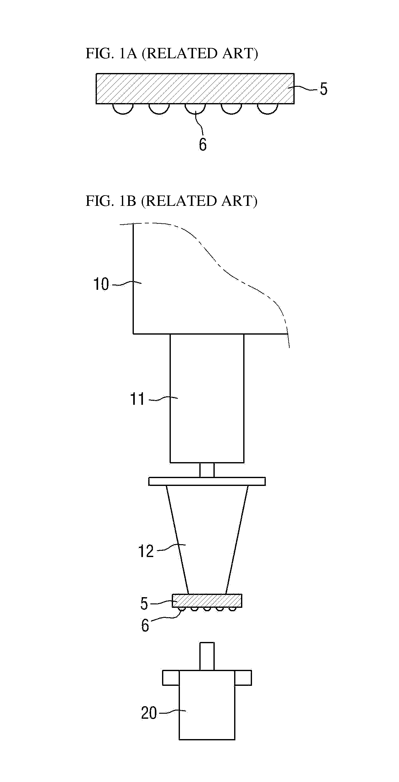
The methods using pneumatic pressure suffer from a high frequency of false defects due to the state of nozzles, whether parts have been picked up by the nozzles, and the instability of reference pneumatic pressure.
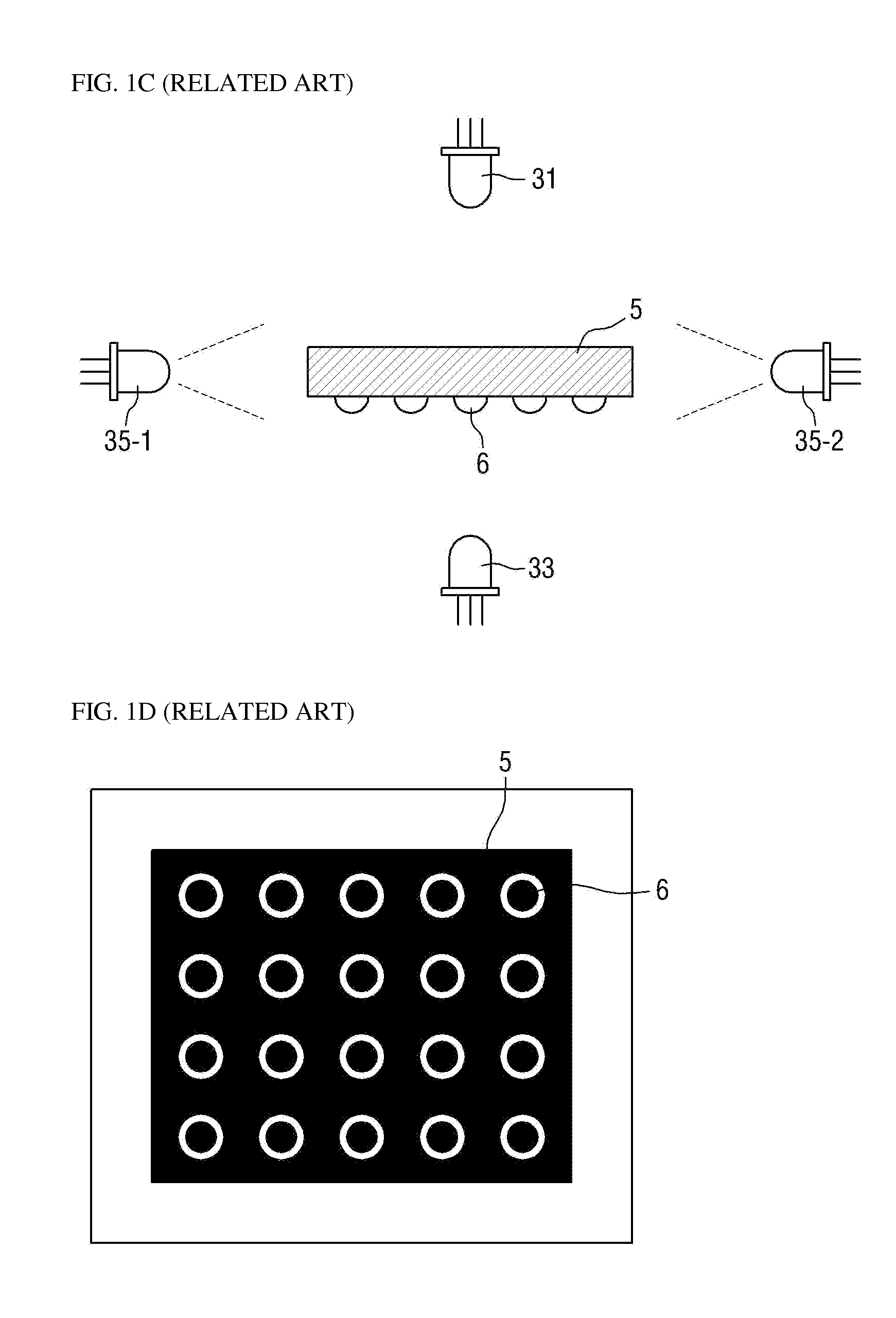
In this structure, however, side lights cannot be arranged in a row or a circular shape due to the limited space in which the side lights for accurately recognizing the edges of parts 5 are installed.

Method used


Image

  • Side light apparatus of chip mounter and light apparatus using the side light apparatus
  • Side light apparatus of chip mounter and light apparatus using the side light apparatus
  • Side light apparatus of chip mounter and light apparatus using the side light apparatus

Examples


Embodiment Construction

[0037]The inventive concept will now be described more fully hereinafter with reference to the accompanying drawings, in which exemplary embodiments of the inventive concept are shown. This inventive concept may, however, be embodied in different forms and should not be construed as limited to the embodiments set forth herein. Rather, these embodiments are provided so that this disclosure will be thorough and complete, and will fully convey the scope of the inventive concept to those skilled in the art. The same reference numbers indicate the same components throughout the specification. In the attached figures, the thickness of layers and regions is exaggerated for clarity.

[0038]It will also be understood that when a layer is referred to as being “on” another layer or substrate, it can be directly on the other layer or substrate, or intervening layers may also be present. In contrast, when an element is referred to as being “directly on” another element, there are no intervening el...


PUM


Abstract

Provided are a light apparatus of a chip mounter which emits light to sides of a plurality of parts picked up by a plurality of nozzles of a chip mounter, the light apparatus including: at least one light module including a plurality of sloping portions each of which includes a plurality of slopes, wherein a slope of the plurality of slopes includes a light source emitting light to a side of a first part picked up by a first nozzle among the plurality of nozzles of the chip mounter.

Description

CROSS REFERENCE TO RELATED APPLICATIONS[0001]This application claims priority from Korean Patent Application No. 10-2012-0028977 filed on Mar. 21, 2012 in the Korean Intellectual Property Office, the disclosure of which is incorporated herein by reference in its entirety.BACKGROUND[0002]1. Field[0003]Apparatuses consistent with exemplary embodiments relate to a light apparatus of a chip mounter, and more particularly, to a side light apparatus of a chip mounter, in which each light source emits light to a side surface of not a spindle or nozzle located directly in front thereof but a spindle or nozzle located obliquely thereto in order to provide optimal lighting in a narrow space.[0004]2. Description of the Related Art[0005]With the development of electronic and communication technology, various electronic devices are becoming smaller and lighter. Accordingly, it is essential to make electronic parts (such as semiconductor chips) embedded in the various electronic devices highly in...

Claims


Application Information

Patent Timeline
Patent Type & Authority Patents(United States)
IPC IPC(8): F21V1/00F21V7/00H05K13/04
CPCF21V7/0066H05K13/0413H05K13/0812F21Y2115/10G01B11/24G01B2210/56G06T2207/30164H05K13/081
Inventor PARK, JAE HYUNBAN, JONG EOK
Owner HANWHA AEROSPACE CO LTD
Learn More