Drilling/reaming tool

a drilling/reaming and drilling technology, applied in the direction of manufacturing tools, drills, wood boring tools, etc., can solve the problems of damage to the wall of the machined hole, and the difficulty of chip transportation, so as to improve the transportation of chips produced during cutting operations.

Active Publication Date: 2015-01-06
KENNAMETAL INC
View PDF37 Cites 3 Cited by
  • Summary
  • Abstract
  • Description
  • Claims
  • Application Information

AI Technical Summary

Benefits of technology

[0007]The present invention improves upon the prior art by providing an improved drilling / reaming tool that, among other things, provides improved transportation of chips produced during cutting operations.
[0009]As a result of such arrangement, the comparatively small reaming chips have to be guided in the reamer flutes only over a small axial length. In particular in the case of relatively deep drilled holes, the reaming chips are then guided away in the usually considerably larger main flute, as a result of which the risk of chips backing up and therefore also jamming of the reaming chips between the hole wall and the tool is avoided. During operation, the reaming chips are therefore preferably transported away first of all in the reamer flutes approximately in the axial direction and are subsequently guided into the main flute, where they are then transported further away together with the drilling chips which are formed by the major cutting edges.
[0023]In principle, any combinations of unequal and equal pitch of the number and distribution of the reaming cutting edges are possible.
[0026]Coolant channels which open at first openings on the end side are preferably formed in the tool basic body. In addition, circumferential-side second openings are provided in the respective reamer flutes close to the reaming cutting edges, in addition to the end-side first openings, with the result that, in addition, coolant is also provided directly at the reaming cutting edges in an effective way. Here, the second openings in the reamer flutes are preferably connected to the (main) coolant channels via channels, in particular in the manner of branch channels or branch bores. Here, the direct arrangement of the reaming cutting edges on the end side and of both the first and second outlet openings achieves cooling of the entire reamer head in an overall very effective and efficient manner, that is to say of the frontmost region of the tool, in which the reamer flutes are formed.

Problems solved by technology

It is to be avoided here, in particular, that a chip is jammed between the wall of the hole and the tool, which would lead to damage of the wall of the machined hole.
Here, transporting away of chips becomes more difficult as the depth of the drilled hole increases.

Method used


Image

  • Drilling/reaming tool
  • Drilling/reaming tool
  • Drilling/reaming tool

Examples


Embodiment Construction

[0034]Directional phrases used herein, such as, for example, left, right, front, back, top, bottom and derivatives thereof, relate to the orientation of the elements shown in the drawings and are not limiting upon the claims unless expressly recited therein. Identical parts are provided with the same reference number in all drawings.

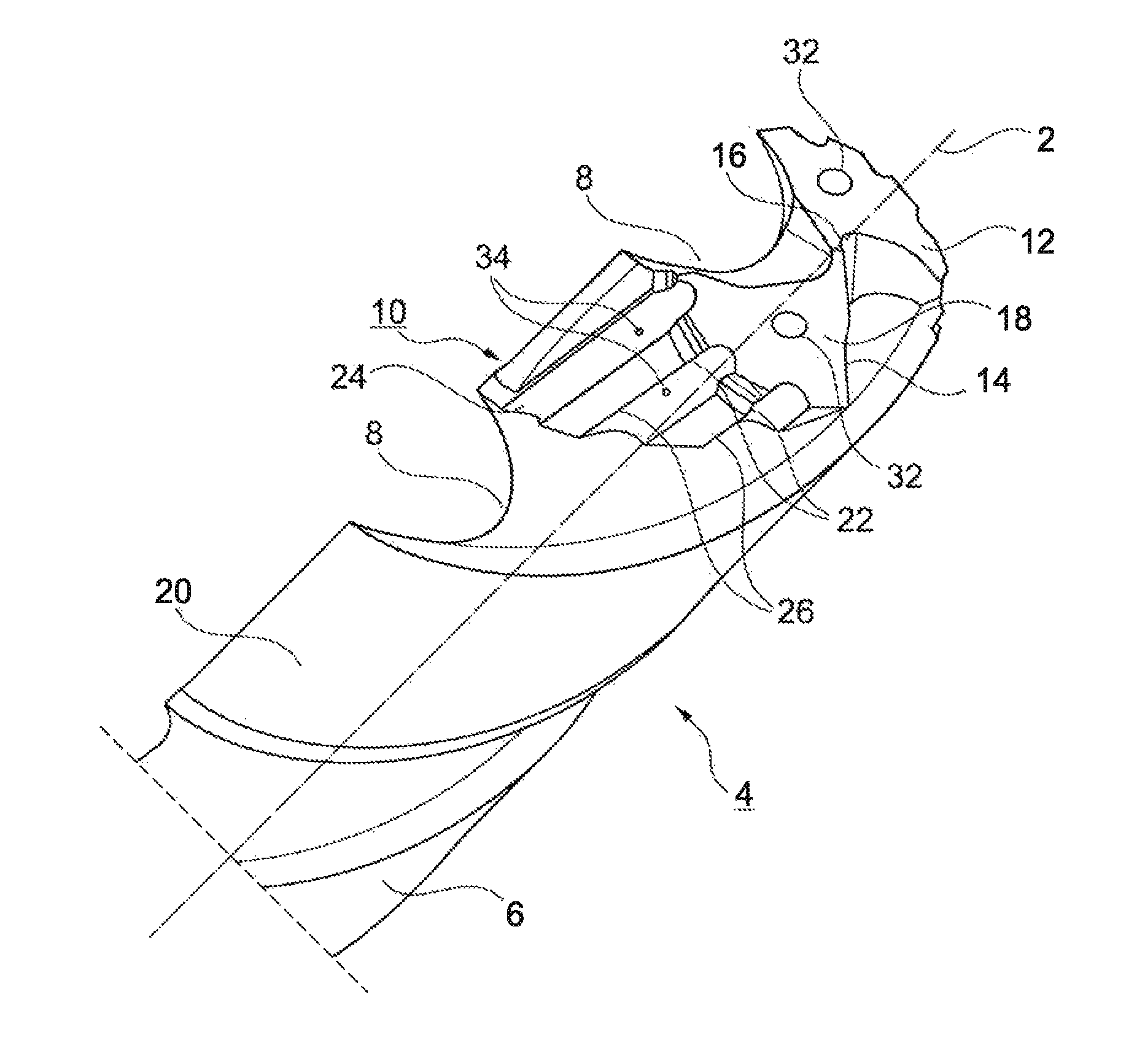
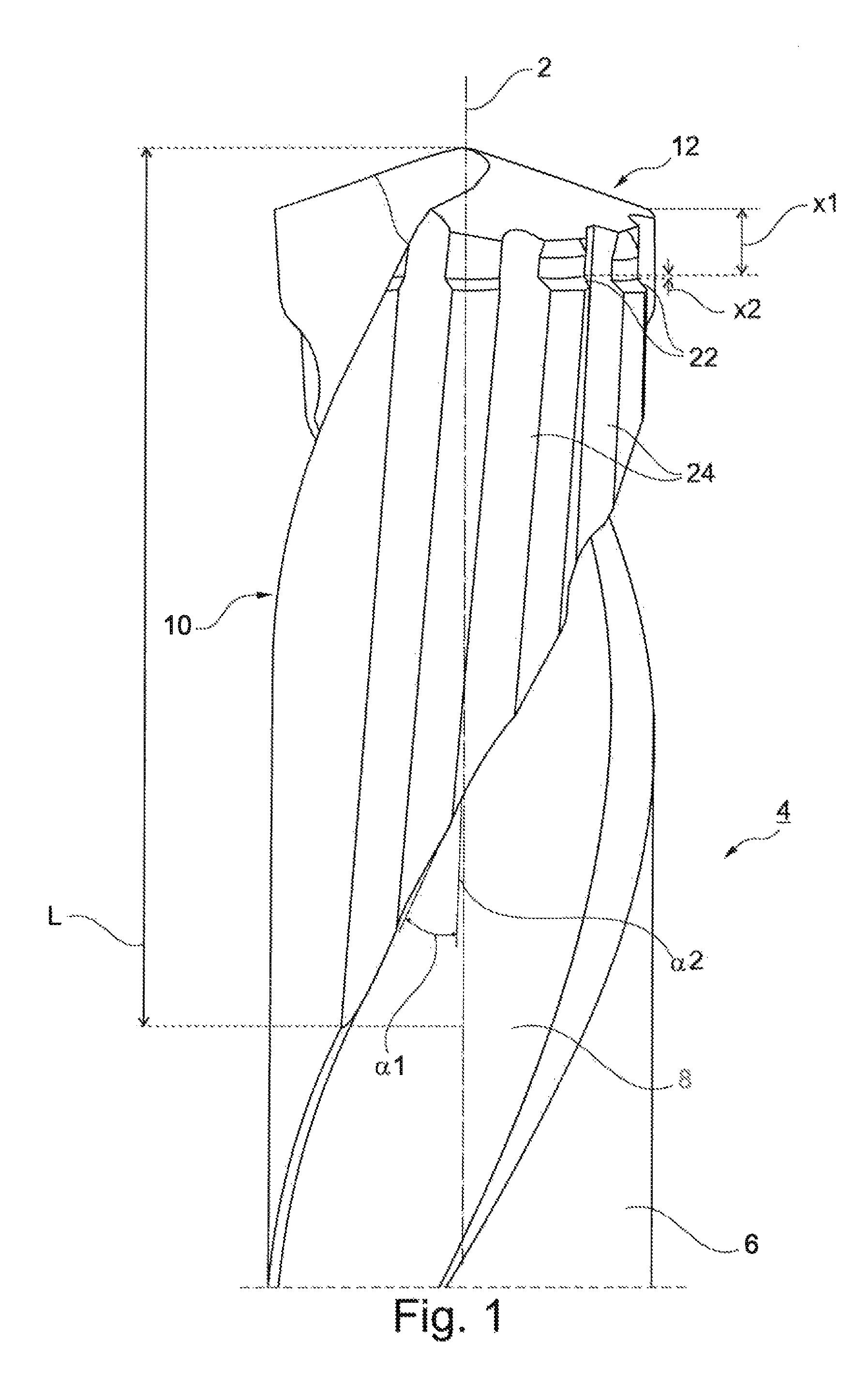
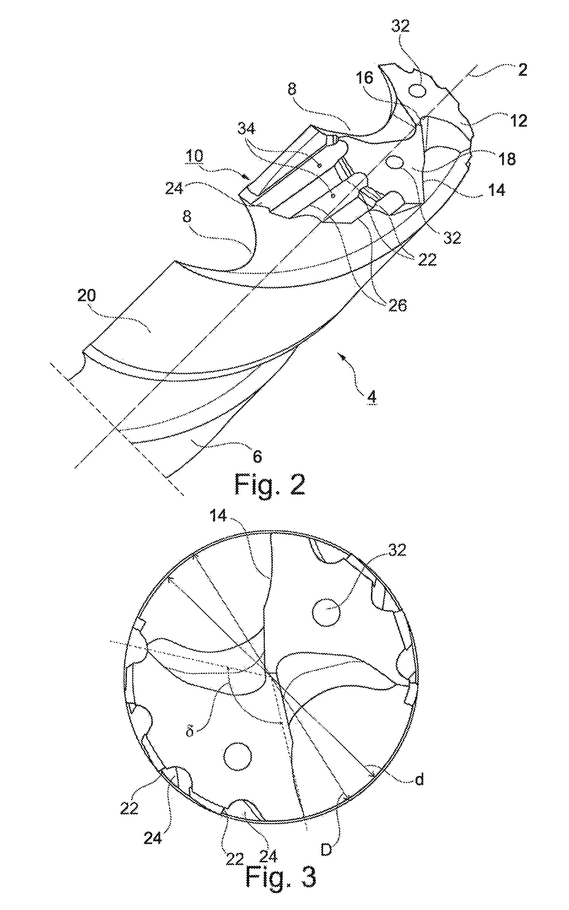
[0035]Referring to FIGS. 1-3, a drilling / reaming tool 4, called a tool for short in the following text, which extends in the longitudinal direction 2 has a basic body 6 which extends in the longitudinal direction 2 and in which, in the exemplary embodiment, two main flutes 8 are made which are wound at a first helix angle α1. In the front region, the tool 4 has a reamer head 10. On its end side, the reamer head 10 is configured as a drill tip 12 which, in the exemplary embodiment, has two major cutting edges 14 (FIGS. 2 and 3) which are connected to one another in the drill center via a chisel edge 16 (FIG. 2). The respective major cutting edge 14 is adj...


PUM

PropertyMeasurementUnit
helix angleaaaaaaaaaa

Abstract

A drilling / reaming tool includes a basic body which extends in a longitudinal direction. The basic body includes at least one end-side drilling major cutting edge, a main flute which is assigned to said drilling major cutting edge and is wound at a first helix angle, and a plurality of reaming cutting edges which are arranged circumferentially on the basic body and have in each case one reamer flute which is assigned to the respective reaming cutting edge and is wound at a second helix angle. The reaming cutting edges adjoin the at least one major cutting edge directly in the longitudinal direction. Each reamer flute is merged into the main flute.

Description

BACKGROUND[0001]1. Field of the Invention[0002]The invention relates generally to rotary cutting tools used to perform drilling / reaming operations.[0003]2. Background Information[0004]An example of a tool upon which the present invention improves is shown, for example, in DE 101 44 241 B4. The drilling / reaming tool which is described in said document has two (drilling) major cutting edges which are in each case assigned a helical main flute which is machined into a basic body of the tool. In addition, three reaming cutting edges which are spaced apart from one another in the circumferential direction are provided on the circumferential side, which reaming cutting edges project somewhat beyond the major cutting edges in the radial direction. Here, the reaming cutting edges adjoin the major cutting edges directly. Each reaming cutting edge is assigned a reamer flute which is likewise formed in a helically extending manner in a land of the basic body between the two main flutes.[0005]D...

Claims


Application Information

Patent Timeline
Patent Type & Authority Patents(United States)
IPC IPC(8): B23D77/00B23B51/08
CPCB23B51/08B23D77/00B23B2251/046B23D2277/52Y10T408/455Y10T408/9097Y10T408/906B23B51/00B23B51/02
Inventor KAUPER, HERBERT RUDOLFSCHWAEGERL, JURGEN
Owner KENNAMETAL INC
Why Eureka
Try Eureka