Vibration system for concrete pipe making machines

a vibration system and concrete technology, applied in the field of concrete pipe making machine vibration system, can solve the problems of not being able to vibrate properly, the center of the side begins to bow, and the central core vibration system has not been used successfully, and achieves the effect of superior, more uniform vibration system

Active Publication Date: 2015-01-06
HAWKEYEPEDERSHAAB CONCRETE TECH INC
View PDF5 Cites 14 Cited by
  • Summary
  • Abstract
  • Description
  • Claims
  • Application Information

AI Technical Summary

Benefits of technology

[0007]The invention provides for a vibration system for adjustable cores for concrete making dry cast machines. Two vertically spaced-apart coupled vibrators are mounted in two opposite corner panels of the core. The vibrators are mounted on shelves welded to the exterior walls that form the mold core. The shelves are also welded to vertical end walls that extend inwardly to form the box-like corner panel. The vertical end walls provide for solid connection to similar end walls on the adjacent side panels. The shelves are reinforced by gussets that are welded to the exterior walls. The corner panels and side panels are secured together by removable fasteners that join the vertical end walls of the corner panels to the corresponding vertical end walls of the side panels. Where the fasteners extend through preformed openings in the vertical supports, bow-tie reinforcements are welded to the inside surfaces of the vertical end walls. Then the fasteners are torqued to at least 400 ft.-lbs. With the invention, both the jacket and core are built rigid enough so they will not bow when filled with concrete. The large vibrators mounted on opposite corners of the rigid core will shake the entire core mass. In building an adjustable core with corner panels and side panels that provide a rigid core structure similar to a solid core, a superior more uniform vibration system is created that vibrates the entire core mass rather than a non-uniform flexing the skin of the core. When the rigid core of the invention is used on conjunction with a jacket mounted with small individual vibrators as shown in FIG. 2, this system compacts the concrete better than known prior art systems.

Problems solved by technology

However, when adjustable forms having removable panels are used, central core vibration systems have not been successfully used because the vibration will cause the panels that form the core to loosen and separate.
If the form set is built too rigid, it will not vibrate properly.
The problem with building the form set flexible enough to vibrate the concrete, is that when concrete is placed in the form, the form begins to bow at the center of the sides.
This is not desired as it leaves bows in the center of the product walls which create point contact at the center of the span when the product is installed in the field.
It also leaves larger than desired gaps between the top and bottom joint rings and the product wall, which gap creates undesirable fins when the joint rings and form set is removed during the final steps of the concrete pipe manufacturing process.
Another problem with this known vibration system for adjustable forms is that it does not provide adequate vibration to properly compact the concrete.
This inadequate vibration contributes to a condition that has been termed “slabbing off”.

Method used


Image

  • Vibration system for concrete pipe making machines
  • Vibration system for concrete pipe making machines
  • Vibration system for concrete pipe making machines

Examples


Embodiment Construction

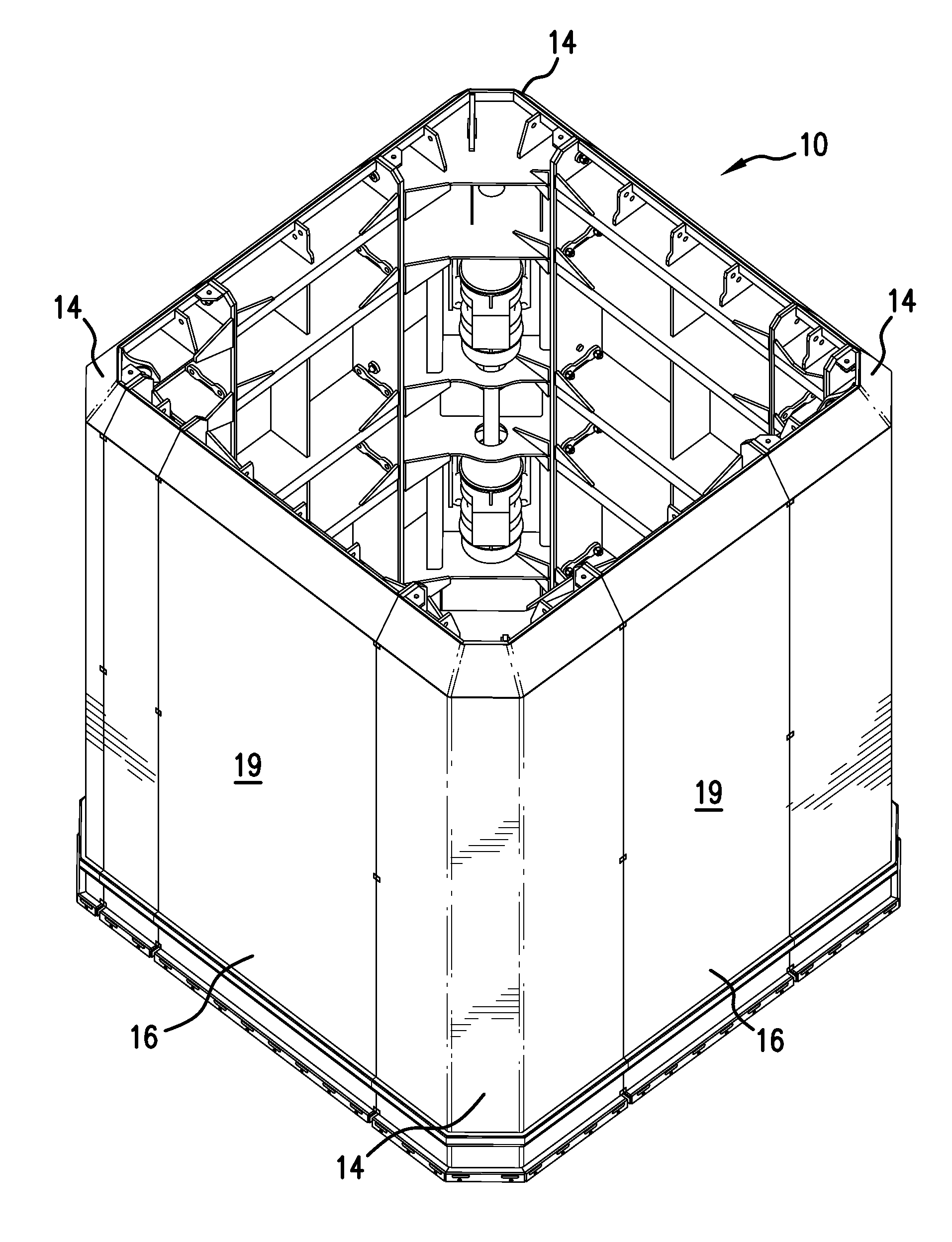
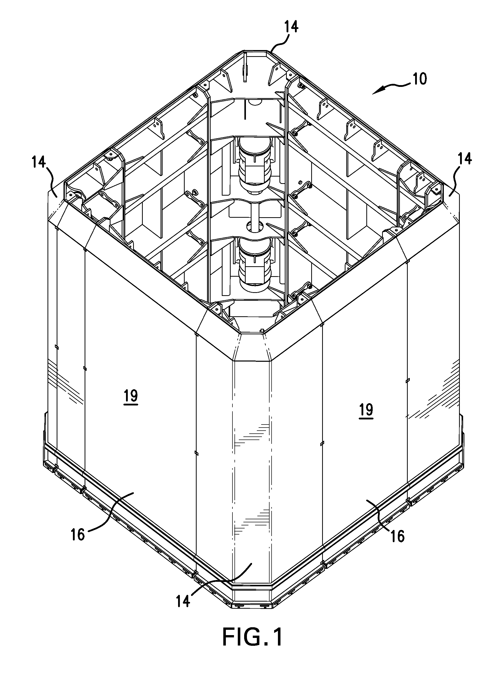
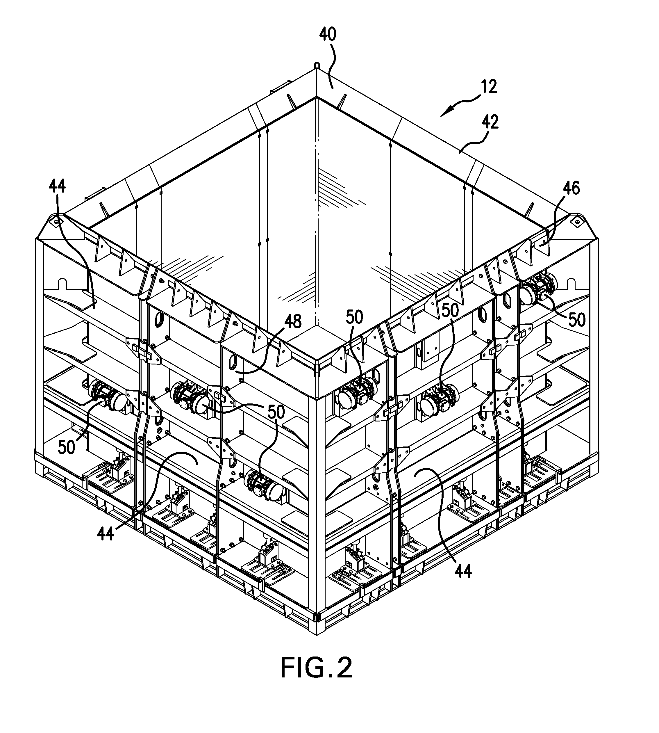
[0014]Referring first to FIG. 1, there is shown an adjustable inner core 10 for a form or mold for producing a square-shaped concrete pipe, for example. As will be understood by those skilled in the art, the core 10 is combined with a jacket 12 (FIG. 2) to create an annular space between them into which space concrete is poured to form the concrete pipe. The core 10 includes corner panels 14 joined to side panels 16 all of which panels have flat, smooth exterior surfaces 19. As shown in FIG. 1, panels 16 are sized to produce a core for square pipe, and when the panels are joined together as shown in FIG. 1, they make up the core 10. When the core 10 is properly positioned inside the jacket 12 and placed on a base (not shown), the core 10 and jacket 12 comprise a mold for the concrete product. As will be understood by those skilled in the art, depending on the manufacturer's production method, the core 10 and jacket 12 either rest on a structure that is a part of the manufacturers pi...


PUM

PropertyMeasurementUnit
massaaaaaaaaaa
sizeaaaaaaaaaa
sizesaaaaaaaaaa

Abstract

A vibration system for concrete pipe making machines using the dry cast method and which employ adjustable molds comprised of corner panels joined to intermediate panels. Two coupled vertically spaced-apart vibrators are mounted in two opposite corner panels of the mold core. The vibrators are mounted on shelves welded to the interior of the walls that form the mold surface. The shelves are also welded to vertical end walls that extend inwardly to form the box-like corner panel. The corner panels and intermediate panels are secured together by removable fasteners that join the vertical end walls of the corner panels to the corresponding vertical end walls of the side panels. The joined corner panels and side panels provide a rigid core structure similar to a solid core and allow the entire core to become the vibration structure.

Description

BACKGROUND OF THE INVENTION[0001]This invention relates to machines and processes for manufacturing concrete products, such as concrete pipe, manholes, catch basins, and the like, and more specifically, the invention relates to the “dry-cast” method of manufacturing concrete products which requires a system for providing vibration to the core and jacket of the concrete mold during the fill and pressure-head cycles of the manufacturing process.[0002]In the dry-cast method of manufacturing, concrete vibration is necessary to consolidate and compact the concrete in the mold prior to curing. The inner mold, or core, of a concrete product mold therefore contains a vibration system which normally consists of eccentric weights mounted on a central shaft, or in some cases vibrators can be mounted on opposite sides of a rigid core for making rectangular shaped products. In any case, the vibrators are typically driven by electric or hydraulic motors. An example of a dry cast concrete pipe mak...

Claims


Application Information

Patent Timeline
Patent Type & Authority Patents(United States)
IPC IPC(8): B28B21/16B28B1/087B28B7/00
CPCB28B21/16B28B1/087B28B7/0029B28B1/08B28B7/0014B28B7/02B28B7/28
Inventor SCHMIDGALL, JON A.
Owner HAWKEYEPEDERSHAAB CONCRETE TECH INC
Why Eureka
Try Eureka