

Ball type continuously variable transmission
a technology of continuous variable transmission and ball type, which is applied in mechanical equipment, transportation and packaging, and transmissions, etc., can solve the problems of increasing the overall complexity and cost, unable to fine-tune the engine speed in the usual transmission, and increasing the complexity of the overall transmission
- Summary
- Abstract
- Description
- Claims
- Application Information
AI Technical Summary
Benefits of technology
Problems solved by technology
Method used
Image

Examples
example 1
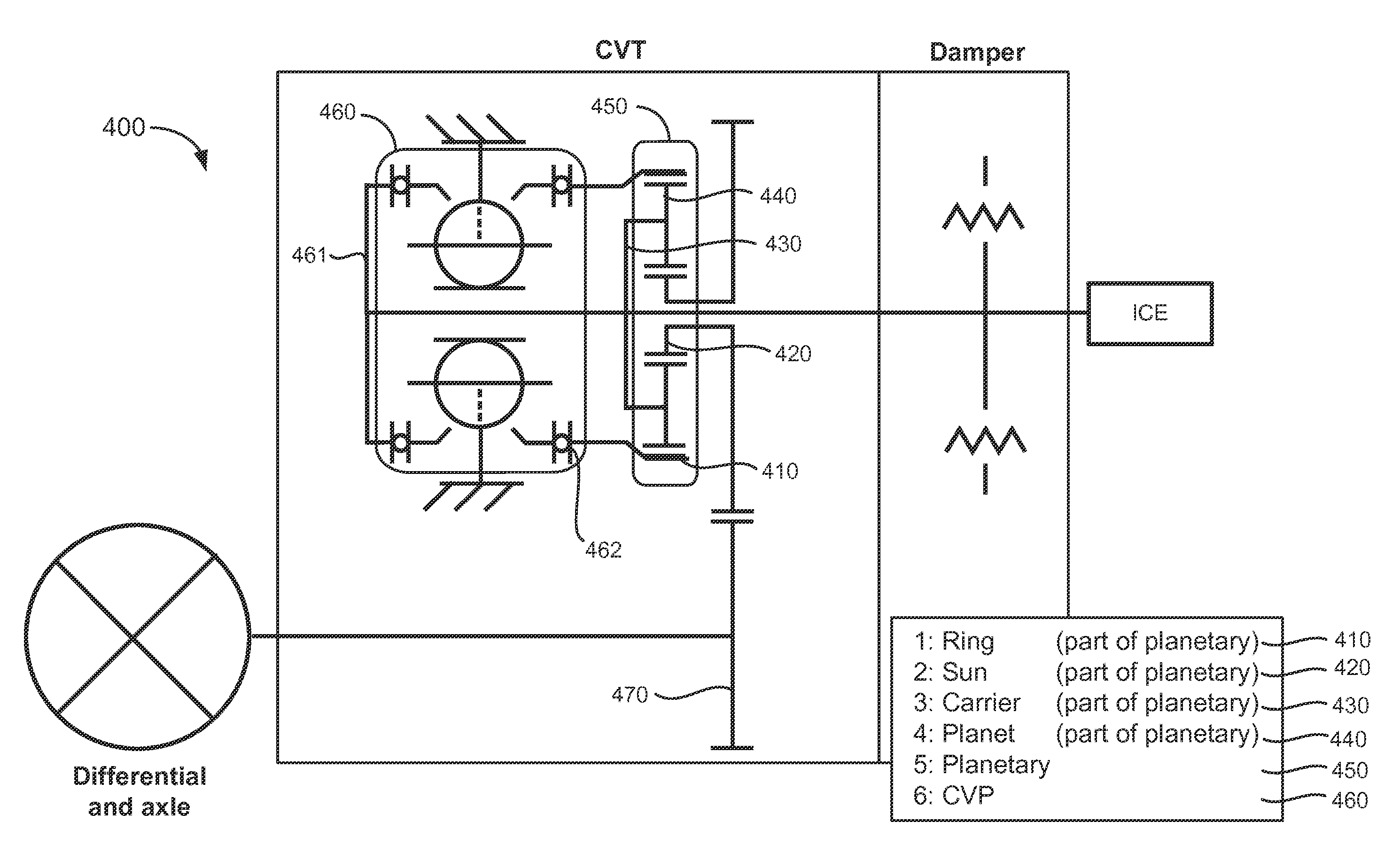
[0056]Some embodiments of the invention are directed to variable transmission configurations that includes a variator (alternatively called a CVP herein) and a planetary gearset that together are able to provide standstill and reverse functions (such as is possible in a typical IVT—infinitely variable transmission). As such, no starting device (like a slipping clutch or a torque converter) is required. Rather, the variable transmission configuration described herein, and shown in an embodiment configuration in FIG. 4, provides the starting function for the vehicle driveline powered by, for example, an engine.
[0057]Thus, certain embodiments of a variable transmission comprise a variator coupled to a planetary gear system. For example, in some embodiments, the planetary gearset is an epicyclic gearset. The planetary gearset comprises the carrier a plurality of planet gears, a sun gear, and a ring gear. The carrier, the sun gear, and the ring gear are rotatably disposed in the transmis...
example 2
[0062]A variant of the previous example comprises a gear ratio at the first ring assembly (input) of the variator, for example, as shown in FIG. 6. As with Example 1, this configuration 600 uses a planetary gearset 650 to provide different power paths and a gear ratio 680 before the first ring assembly 661 of the variator 660. Thanks to the planetary gearset, the configuration uses only a variator yet is able to provide standstill and reverse function as an infinitely variable transmission would. No starting device like a slipping clutch or torque converter is required, since the infinitely variable transmission of the embodiment CVT described in this example, at least, takes care of the starting function. The added gear ratio gives the ability to increase the coverage of reverse speeds and also decreases the torque on the variator.
[0063]Adding a gear ratio 680 greater than 1 to the input of the variator (the input to the variator depicted on the left of the variator 660 in FIG. 6) ...
example 3
[0070]An internal speed ratio is alternatively created using an asymmetric variator rather than the power split configurations of Example 1 and Example 2. Such a configuration eliminates need for the ratio gears and countershaft or planetary gear set of Example 2, thus reducing the parts of the overall variable transmission while providing the same functionality. Additionally, an asymmetric variator that changes alpha angles (described elsewhere herein) could be used in many other cases, increasing the spread, or giving better efficiency for a certain range of speed ratios
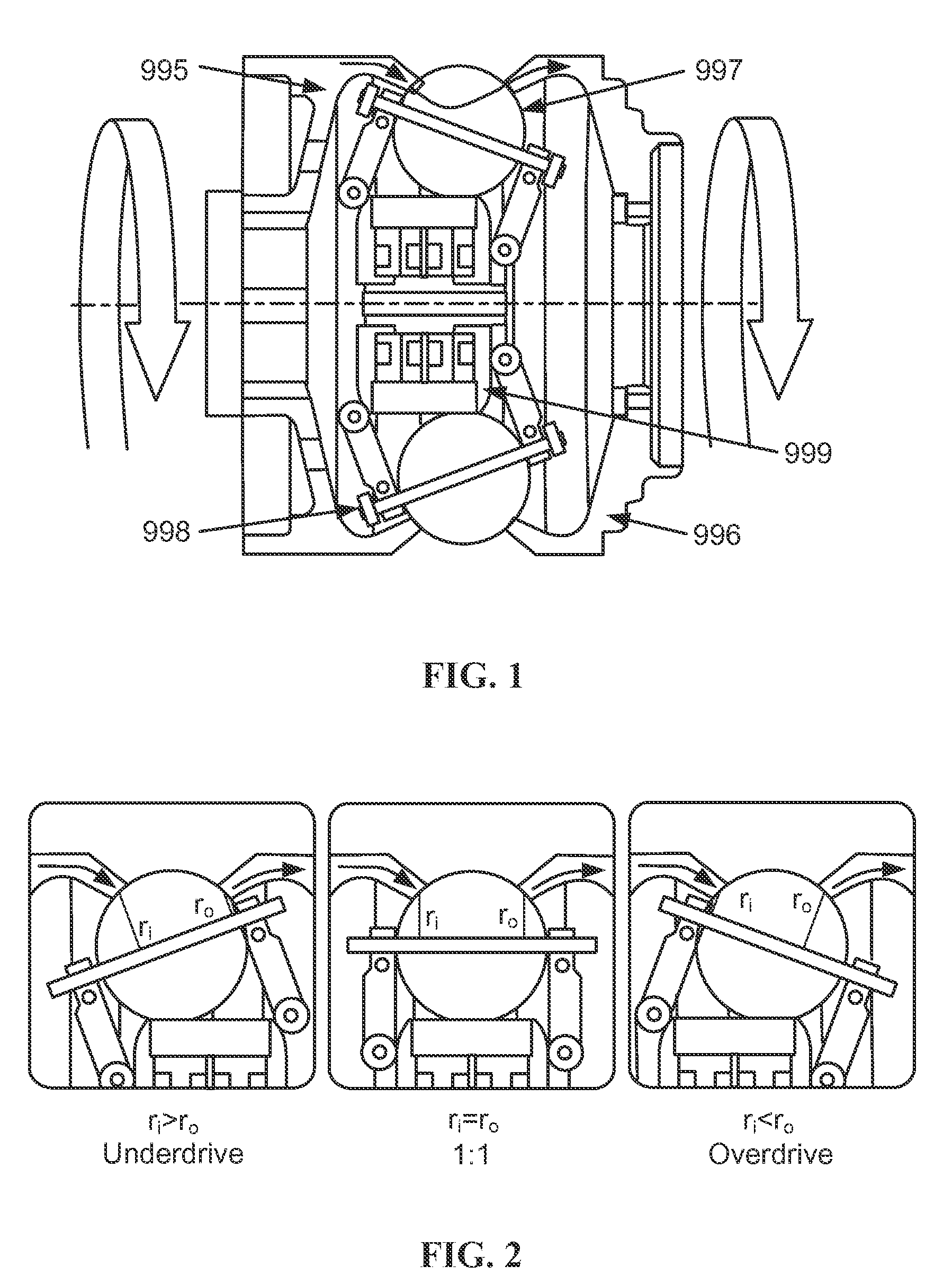
[0071]Thus, some embodiments of a variable transmission that includes a biasing gear ratio on the variator. This is optionally achieved by modifying the variator to produce an asymmetric variator design. FIG. 8 shows a standard ball variator 800 used in the variable transmission. The first ring assembly 801 (input ring) and second ring assembly 802 (output ring) are mechanically coupled to each variator ball 803 at...
PUM
 Abstract
Description
Claims
Application Information