Wound support for use in vacuum therapy of wounds

a vacuum therapy and wound technology, applied in the field of wound support, can solve the problems of pain in the patient and the severe reduction of the therapeutic effect of this measur

Inactive Publication Date: 2015-01-06
PAUL HARTMANN AG
View PDF13 Cites 10 Cited by
  • Summary
  • Abstract
  • Description
  • Claims
  • Application Information

AI Technical Summary

Benefits of technology

[0006]Because inventively a sleeve is disposed in the through-hole of the foam-based wound support, simple and secure insertion of the wound-facing end section of the fluid feed tube can be ensured. Thus this end section is given a predefined orientation in the wound space, without it being necessary for the treating person to perform complicated handling of the tube components in the wound space or inside the wound support when applying the components for the vacuum therapy. Moreover, there is less danger that arranging the components will result in painful discomfort of the patient. It thus proves particularly advantageous that, due to the inventive disposition of the sleeve, the end section of the fluid feed tube does not have to project beyond the side of the wound support facing the wound base, so that irritation of the wound base resulting from the fluid feed tube can be avoided. Even so, according to the invention, it can be ensured that liquid or gaseous media that are conveyed via the fluid feed tube, such as rinsing liquid or oxygen, for example, can be conveyed all the way to the wound base, where they are particularly needed. Because if, for example, rinsing liquid or liquid with pharmaceutically effective substances that support wound healing are only conveyed to a region of the wound support facing away from the wound base to be then immediately suctioned out again through a suction tube, the therapeutic effect of this measure is severely diminished. The inventive wound support, on the other hand, ensures that the conveyed fluid can reach the wound base where it can have its intended therapeutic effect. Even if merely rinsing fluid, for example, in the form of Ringer's solution, is applied, effective rinsing and therefore cleansing of the wound space can be achieved.
[0008]In a further embodiment of the invention, it proves advantageous if the sleeve has a collar at least on one side, preferably on both sides of the foamed material, with which the sleeve rests axially against a side of the foamed material that surrounds the opening with respect to a longitudinal axis of the sleeve. By this means, an even and an edge-free transition from the sleeve to the foamed material of the wound support can be achieved, and insertion of the end section of the fluid feed tube can be implemented more simply. It further proves advantageous if the collar is closed around its entire circumference.
[0009]According to a further inventive embodiment of particular significance, it is advantageous if the length of the sleeve can be altered so that the sleeve can be adapted to the compression or contraction of the foamed material of the wound support. For this, the sleeve according to a further inventive idea can have two sliding telescopic sleeve sections that slide toward each other along a sleeve longitudinal axis. According to another inventive idea it is possible for the sleeve to comprise two sleeve sections that can slide toward each other by means of a bellows-type coupling along the sleeve longitudinal axis.
[0061]According to a preferred embodiment of the inventive connecting device it has proved advantageous if the fluid feed tube extends parallel to the suction tube at least in the region of the connecting device. This simplifies attachment on the vacuum dressing but also the disposition and placement of the conduits around the patient. Irrespective of this, it also proves practical if the conduits extend parallel in the region of the support means.

Problems solved by technology

Moreover, there is less danger that arranging the components will result in painful discomfort of the patient.
Because if, for example, rinsing liquid or liquid with pharmaceutically effective substances that support wound healing are only conveyed to a region of the wound support facing away from the wound base to be then immediately suctioned out again through a suction tube, the therapeutic effect of this measure is severely diminished.

Method used


Image

  • Wound support for use in vacuum therapy of wounds
  • Wound support for use in vacuum therapy of wounds
  • Wound support for use in vacuum therapy of wounds

Examples


Embodiment Construction

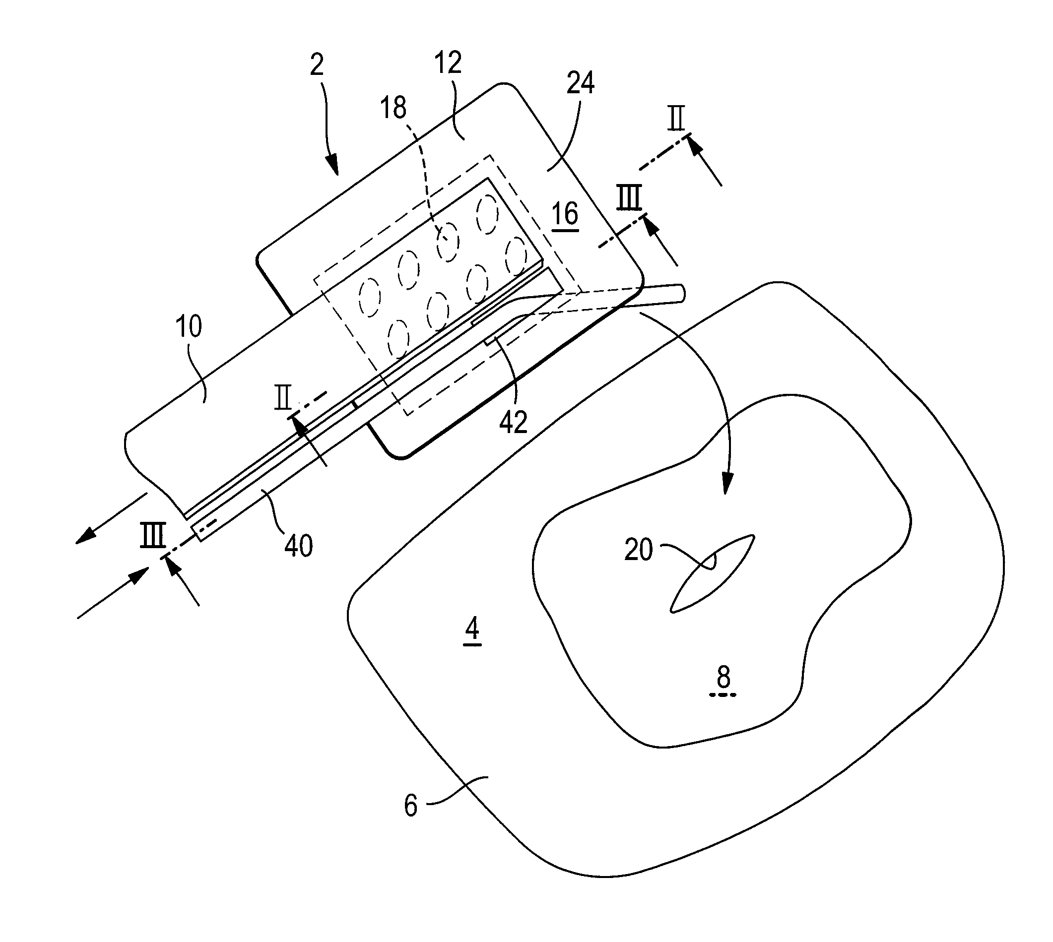
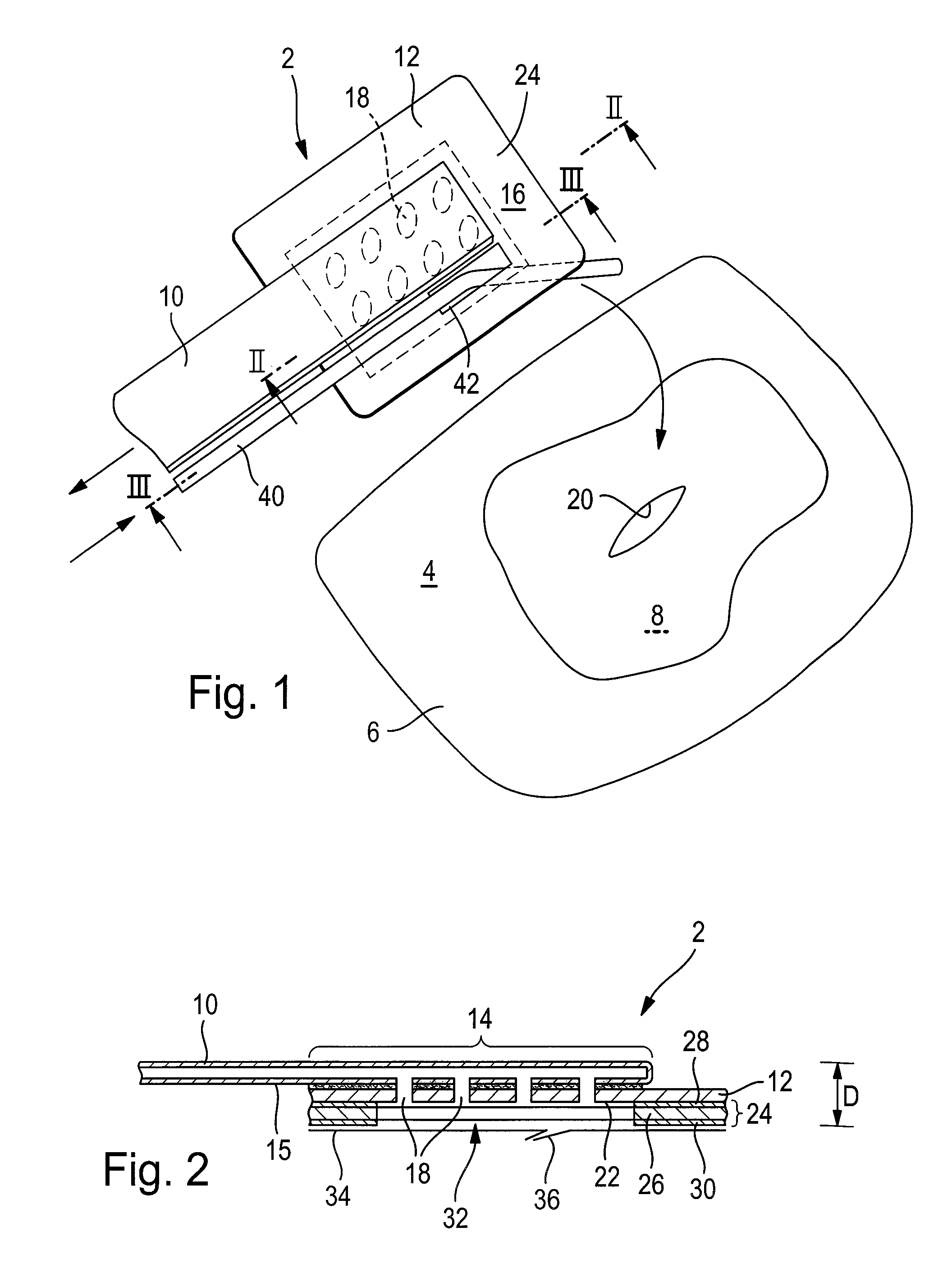
[0069]The figures show different views of a connecting device overall designated with the reference sign 2 for use in the vacuum treatment of wounds. The illustrated connecting device 2 is applied to an upper side 4, facing away from the wound, of a schematic vacuum dressing 6, which overlaps a wound 8 to be treated, which seals vacuum tight with respect to the atmosphere and which is fixed by adhesive means in a way still to be described.

[0070]The connecting device 2 comprises a flat conduit shown as an example in the illustration, in the shape of a suction tube 10 made of an elastomer flexible material and a two-dimensionally extending, plate-shaped support means 12, which holds and supports the flat suction tube 10, so that the pressure and torsional forces applied to the suction tube 10 are introduced evenly into the large-area support means 12 and can be taken up by the latter.

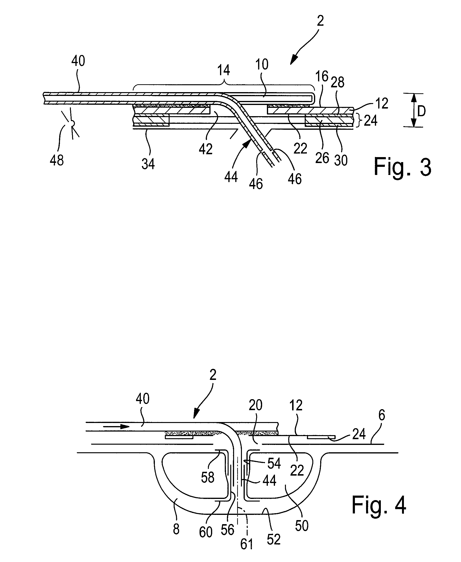
[0071]The suction tube 10 is sufficiently flat that in a longitudinal end section 14, preferably almos...


PUM


Abstract

A wound support (50) for use in the vacuum therapy of wounds, can be disposed in its intended use in a wound space underneath a vacuum dressing (6) sealing the wound space with respect to the atmosphere in an essentially vacuum-tight manner, wherein the wound space can communicate with a suction tube (10) to which a vacuum can be applied through an opening (20) in the vacuum dressing (6). The wound support (50) comprises a flexibly compliant foamed material and has a through-hole (54) that extends in the direction of the wound depth, which is used to insert or pass through a wound-side end section (44) of a fluid feed tube (40). A sleeve (56) is disposed in the through-hole (54) into which this end section (44) can be inserted.

Description

[0001]This application claims benefit of 61 / 573,185 filed on Sep. 21, 2011 as well as Paris Convention priority of DE 10 2011 082 347.6 filed on Sep. 8, 2011 the entire disclosures of which are hereby incorporated by reference.BACKGROUND OF THE INVENTION[0002]The invention relates to a wound support for use in the vacuum therapy of wounds, wherein the wound support can be disposed in its intended use in a wound space underneath a vacuum dressing sealing the wound space with respect to the atmosphere in an essentially vacuum-tight manner, and wherein the wound space can communicate with a suction tube to which a vacuum can be applied through an opening in the vacuum dressing, wherein the wound support comprises a flexibly compliant foamed material. Wound supports for use in the vacuum therapy of wounds have been previously described in e.g. WO 2004 / 037334 and WO 2010 / 033272.[0003]The importance of the vacuum therapy of wounds, in particular, of wounds that are deep and whose healing ...

Claims


Application Information

Patent Timeline
Patent Type & Authority Patents(United States)
IPC IPC(8): A61M1/00
CPCA61M1/0088A61M1/0084A61M1/916A61M1/92A61M1/912A61M1/915A61F13/00068A61F13/0216
Inventor CROIZAT, PIERREECKSTEIN, AXEL
Owner PAUL HARTMANN AG
Why Eureka
Try Eureka