Linear light source apparatus and image reading apparatus

a light source and image technology, applied in the direction of electrical devices, pictoral communication, etc., can solve the problems of reducing the illumination per unit area and the reduction of the quantity of light reaching the document g, and achieve the effect of facilitating an increase in the light quantity

Inactive Publication Date: 2015-01-06
ROHM CO LTD
View PDF18 Cites 5 Cited by
  • Summary
  • Abstract
  • Description
  • Claims
  • Application Information

AI Technical Summary

Benefits of technology

[0012]With this configuration, light that has been reflected by the end face in the third direction can easily reach the light-reflecting portion, and therefore the quantity of light that is reflected by the light-reflecting portion in the second direction can easily increase. Accordingly, the linear light source device of the present invention can facilitate an increase in light quantity.

Problems solved by technology

On the other hand, extending the irradiation area of the linear light source device 90 in the y′-direction poses a problem in that the illuminance per unit area decreases, and it is desired to efficiently emit the light from the LED unit 92 in an emitting direction L.
Further, the image reading device X has another problem in that part of the light emitted from the linear light source device 90 is blocked by the lens array 94, resulting in a reduction in the quantity of light reaching the document G.

Method used


Image

  • Linear light source apparatus and image reading apparatus
  • Linear light source apparatus and image reading apparatus
  • Linear light source apparatus and image reading apparatus

Examples


Embodiment Construction

[0050]Preferred embodiments of the present invention will now be specifically described below with reference to the accompanying drawings.

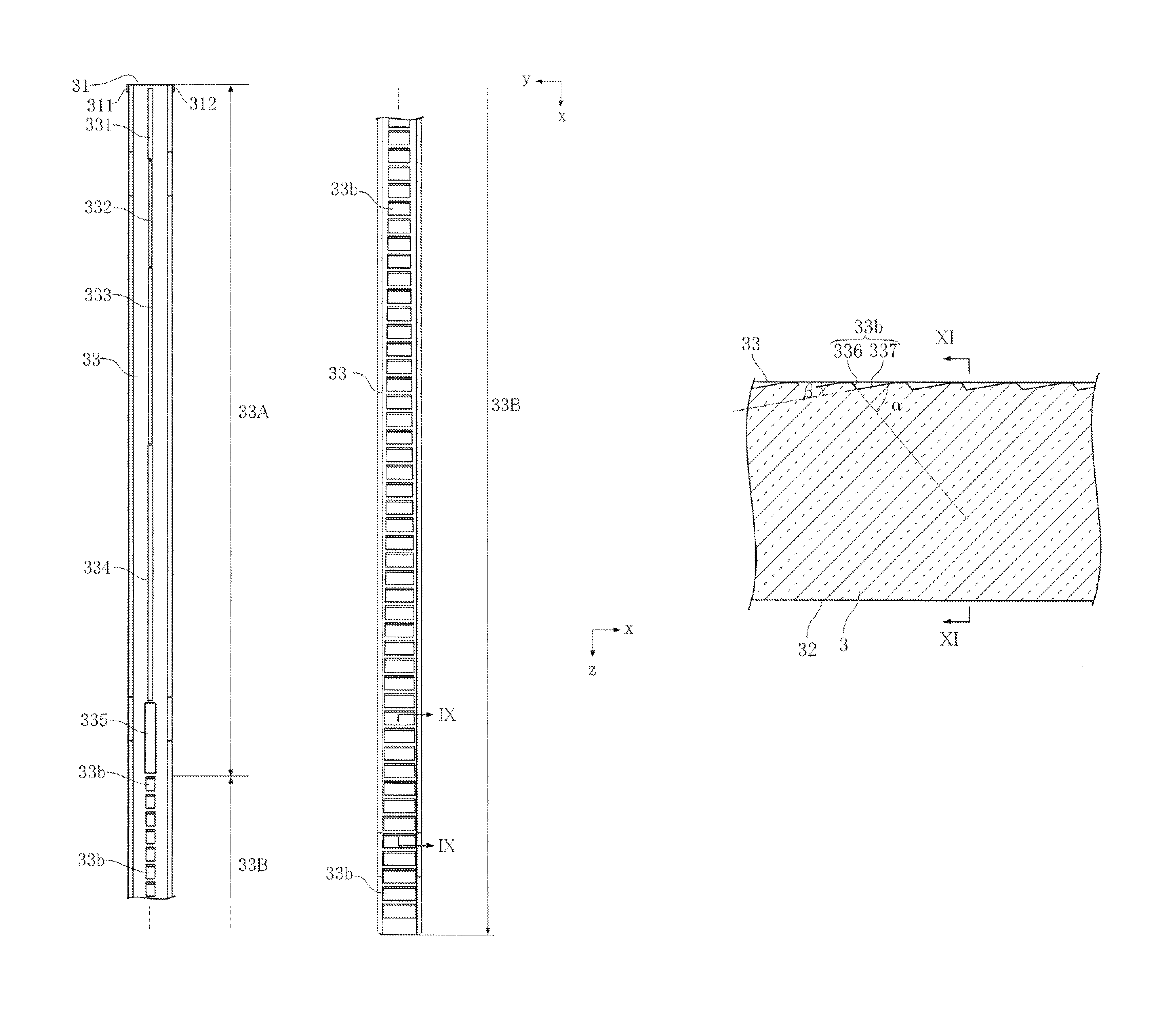
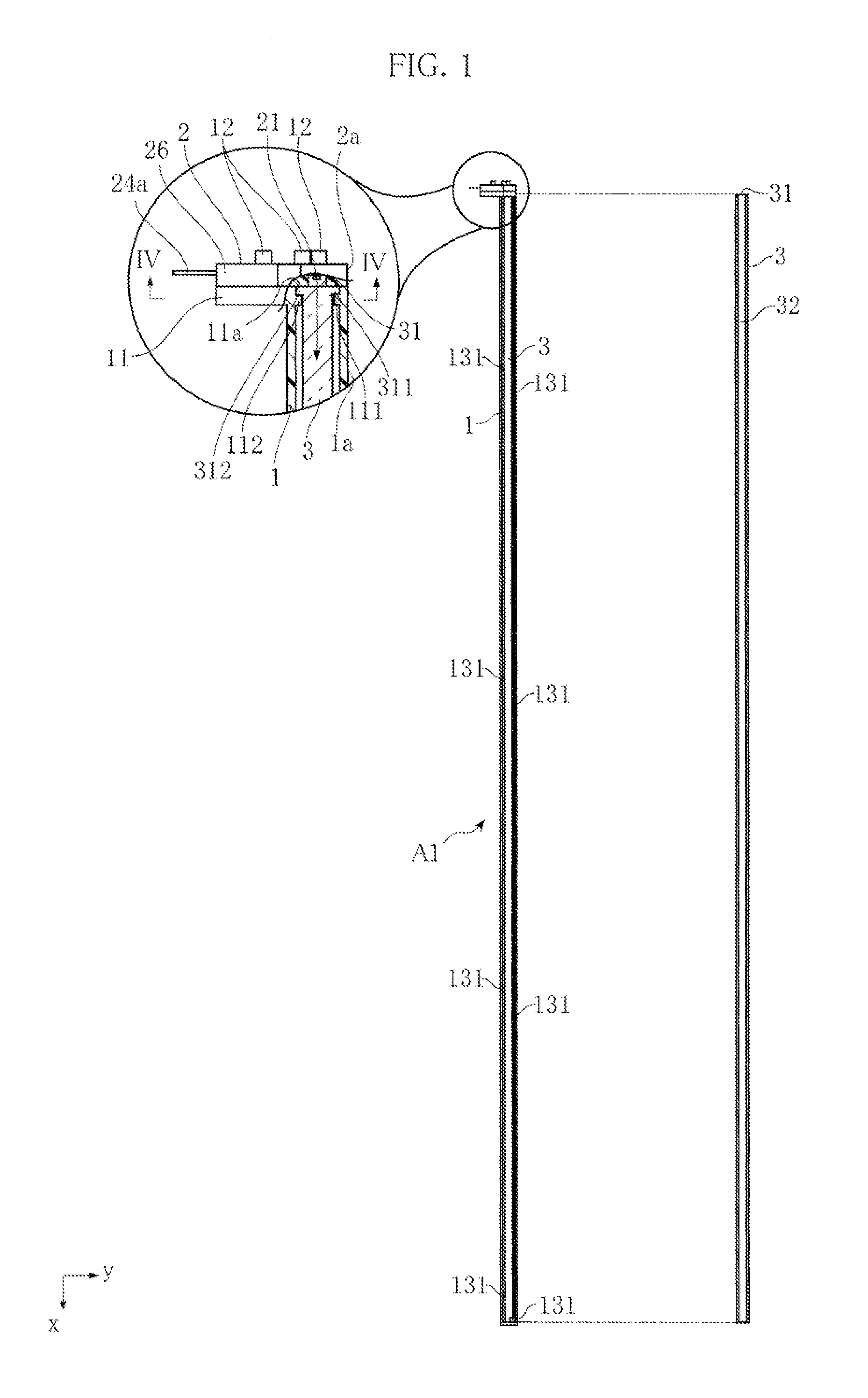
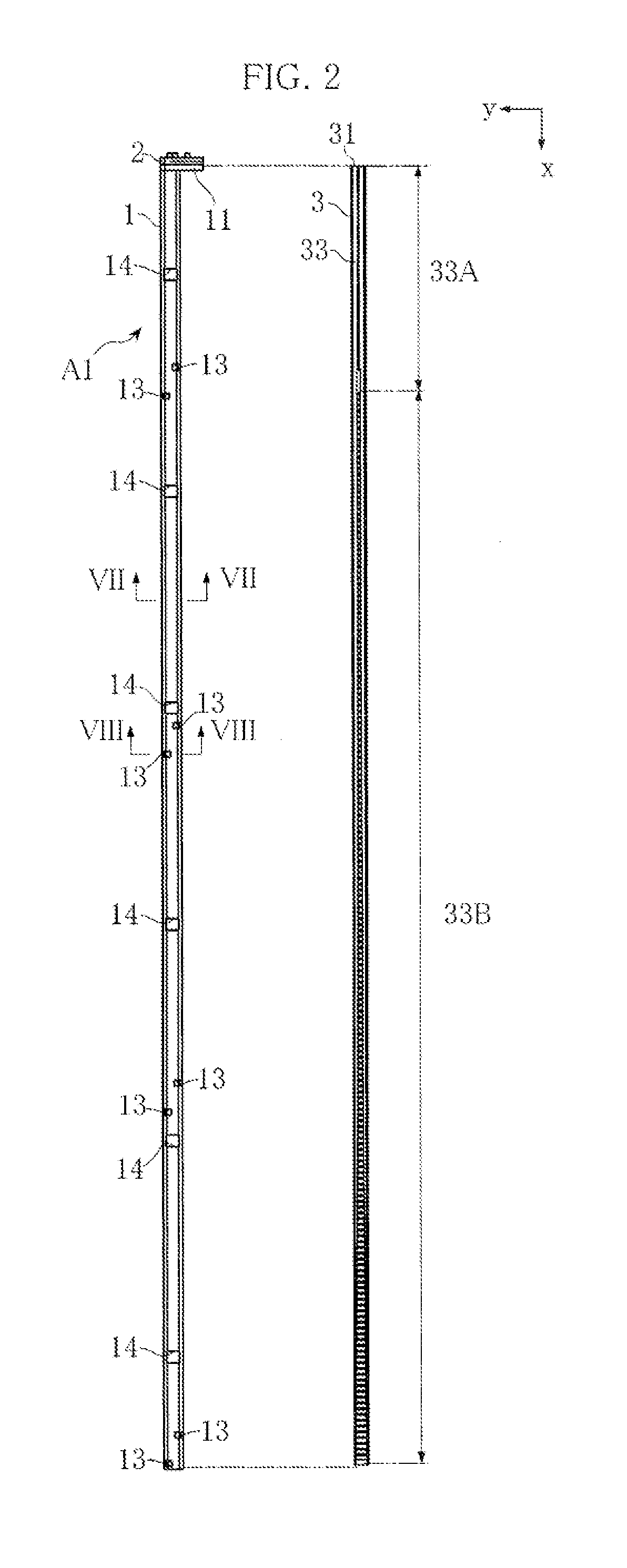
[0051]FIGS. 1 to 11 show a linear light source device according to a first embodiment of the present invention. As shown in FIGS. 1 and 2, a linear light source device A1 includes a white case 1 formed in the shape of an elongated rod elongated in the x-direction, an LED unit 2 attached at one end of the white case 1 in the x-direction, and a light-guiding member 3 that can be housed in the white case 1. FIG. 1 also shows the light-guiding member 3 housed in the white case 1. FIGS. 12 and 13 show an image reading device B incorporating the linear light source device A1. The image reading device B includes a lens array 4, a light-receiving element 5, a substrate 6 for supporting the light-receiving element 5, a case 7 for housing these components, and a glass cover 8 on which a document G is placed. The glass cover 8 is attached to the casing porti...


PUM


Abstract

A linear light source device illuminates a document properly, and an image reading device includes such a light source device. The light source device includes a light source and a light-guiding member. The light-guiding member introduces the light emitted from the light source from one end portion in x-direction, cause the light to travel in x-direction, and emits the light from a light exit portion at one end in z-direction, which is orthogonal to x-direction. The light-guiding member includes, at the other end in z-direction, a light-reflecting portion that reflects light to the light exit portion. One end face of the light-guiding member in y-direction, which is orthogonal to x- and z-directions, is inclined so as to become closer to the other end face in y-direction with decreasing distance from the light exit portion in z-direction. This allows light to easily travel to the light-reflecting portion.

Description

BACKGROUND OF THE INVENTION[0001]1. Field of the Invention[0002]The present invention relates to a linear light source apparatus and an image reading device including the linear light source apparatus.[0003]2. Description of Related Art[0004]An image reading device for reading documents is incorporated in, for example, a facsimile machine, a copier, and a scanner device. FIG. 20 shows an example of such an image reading device (for example, see JP 2007-27137A). The image reading device X shown in FIG. 20 includes a linear light source device 90, a lens array 94, a light-receiving element 95, a substrate 96, a case 97, and a glass cover 98 for loading a document G. The image reading device X reads the document G by illuminating the document G with the linear light source device 90 and guiding the light reflected from the document G through the lens array 94 to the light-receiving element 95.[0005]FIG. 21 is a perspective view of the linear light source device 90. As shown in FIG. 21,...

Claims


Application Information

Patent Timeline
Patent Type & Authority Patents(United States)
IPC IPC(8): H04N1/04H04N1/46H04N1/028
CPCH04N1/02815H04N1/02825H04N1/02835
Inventor MINAMIKAWA, YOSHINORIHORIO, TOMOHARUKONDO, OKIMOTO
Owner ROHM CO LTD
Why Eureka
Try Eureka