Change of spring force by means of levers

a technology of spring force and lever, which is applied in the field of spring system, can solve the problems of springs and/or dampers that must be replaced, require repair, and are expensive and time-consuming to produce and maintain, and achieve the effect of simple, accurate and economic production

Inactive Publication Date: 2015-01-13
GRAMMER AG
View PDF8 Cites 29 Cited by
  • Summary
  • Abstract
  • Description
  • Claims
  • Application Information

AI Technical Summary

Benefits of technology

[0008]This solution is advantageous in relation to devices known from the prior art as it simple and cheap to produce and easy to operate.
[0032]In a further preferred embodiment of the present invention, the deflection means is formed plate-like at least in sections and / or preferably in sections rod-like and particularly preferably lever-like. This is advantageous as such plate-like and / or rod-like and lever-like means are simple, accurate and economic to produce.

Problems solved by technology

Such spring systems require a complex control of the air spring and the damper and are therefore cost- and time-intensive to produce and maintain.
Such spring systems also have the disadvantage that after a certain time they require repair, and where applicable the air springs and / or dampers must be replaced.
Furthermore the spring systems known from the prior art are often very complex to adjust.

Method used


Image

  • Change of spring force by means of levers
  • Change of spring force by means of levers
  • Change of spring force by means of levers

Examples


Embodiment Construction

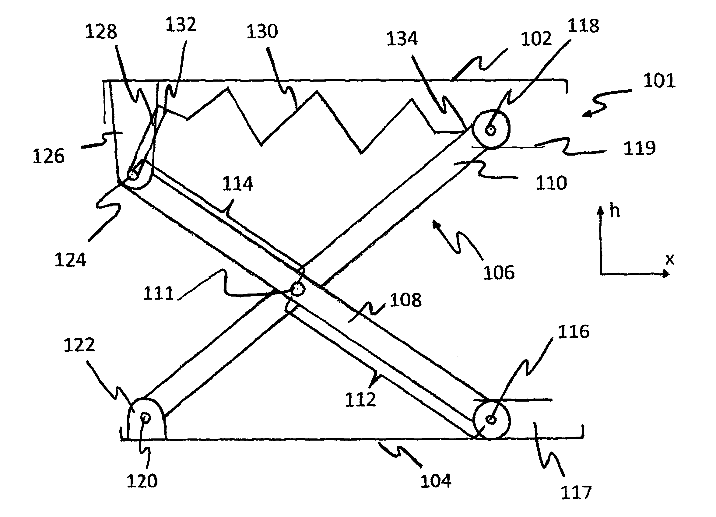
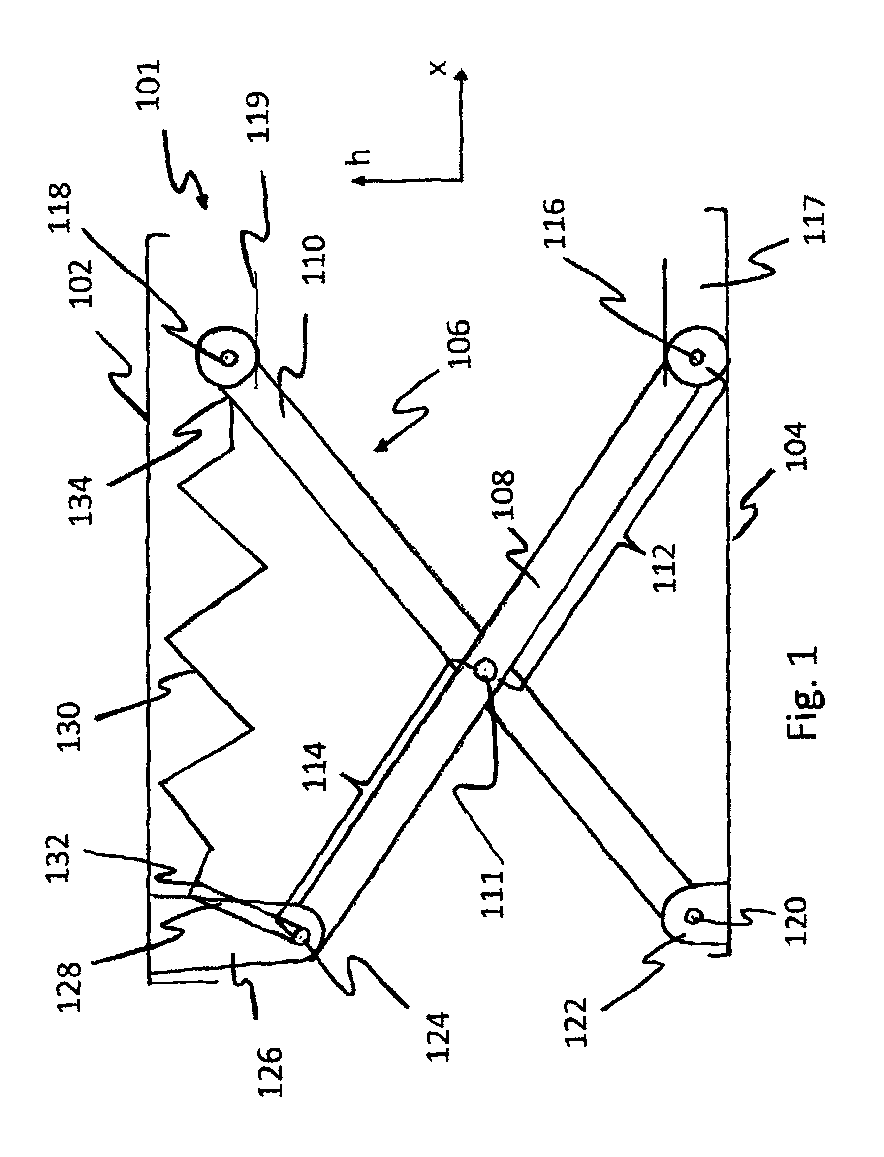
[0043]FIG. 1 shows a diagrammatic view of a lower section of a vehicle seat or a vehicle cab of a vehicle, wherein the spring system 101 can be set to oscillate in the vertical direction. The spring system 101 has an upper arrangement area 102 and a lower arrangement area 104 which are connected together via a scissors-type frame 106. The scissors-type frame 106 comprises a first segment 108 and a second segment 110 that are connected together via a central axis 111.

[0044]FIG. 1 shows that the first segment 108 has a first section 112 that is longer than a second section 114. It is however also conceivable that the second section 114 is longer than the first section 112 or the two sections 112, 114 are the same length.

[0045]The first segment 108 has a first axis 116 that can be displaced in the x-direction. It is conceivable that a wheel is provided on the first axis 116 mounted movable in the lower bearing 117 or a slide element is provided on the first axis 114 mounted sliding in ...


PUM


Abstract

The invention concerns a spring system for use in vehicles for adjustment of the suspension characteristics, comprising at least one spring element to provide a spring force, an upper and a lower arrangement area to receive forces, a scissors-type frame arranged between the upper and the lower arrangement area for coupling the spring element with at least one force acting on one of the arrangement areas. According to the invention the spring element is coupled with a deflection means to influence the spring force and between the deflection means and a segment of the scissors-type frame an active connection can be created to transmit forces.

Description

CROSS REFERENCE TO RELATED APPLICATIONS[0001]This application is a convention application of German Application Serial Number 10 2009 031 411.3, filed Jul. 2, 2009 and German Patent Application No. 10 2009 040 010.9, filed Sep. 3, 2009, which applications are hereby incorporated by this reference in their entirety.BACKGROUND OF THE INVENTION[0002]The invention concerns a spring system for use in vehicles, in particular for vehicle seats and / or vehicle cabs, according to the preamble of claim 1.[0003]Spring systems, in particular for vehicle seats, are known in many variants. For example, very often a pneumatic spring is arranged between two suspension parts, namely a lower part and an upper part on which the actual vehicle seat is mounted, and in addition a gas damper element is fitted in order to absorb the vibration movement which can be initiated both from above by the driver and from below by the chassis. Such spring systems require a complex control of the air spring and the da...

Claims


Application Information

Patent Timeline
Patent Type & Authority Patents(United States)
IPC IPC(8): B60N2/54B60N2/50
CPCB60N2/502B60N2/505B60N2/508B60N2/544B60N2/509
Inventor KOHL, JOSEFDEML, JOHANN
Owner GRAMMER AG
Why Eureka
Try Eureka