Lighting installation and method for using the same

a technology for lighting installations and installations, applied in outdoor lighting, electric lighting without self-contained power, lighting and heating apparatus, etc., can solve the problems of affecting the size of the installation and its stability during operation, affecting the deployment time of the installation, and affecting the reliability and stability of the lighting installation. , to achieve the effect of improving the reliability and stability of the lighting installation and increasing the convenience of handling i

Inactive Publication Date: 2015-01-13
NALITCHAEV BORIS VLADIMIROVITCH +1
View PDF9 Cites 2 Cited by
  • Summary
  • Abstract
  • Description
  • Claims
  • Application Information

AI Technical Summary

Benefits of technology

[0007]The primary purpose of the invention is to improve the reliability and stability of the lighting installation, increasing the convenience of handling thereof and providing protection thereof during transportation. Other purposes can be found by a skilled artisan upon learning the present disclosure.

Problems solved by technology

The inflatable supports of these lighting installations have means for maintaining their stable vertical position and these stabilizing means are tension members in RU 2192581C1 and U.S. Pat. No. 6,322,230B1; the tension members are linked to the support and to the ground, and this substantially increases complexity of the installation design.
Stability of this installation depends on design features of the base having a rest which negatively influences the size of the installation and its stability during operation.
The above drawback is substantial when the installation has to be urgently delivered to emergency locations and a comparatively big size of the base negatively influences the deployment time of the installation and hampers its moving during operation.
While being urgently delivered, the installation is not protected against a mechanical effect which often leads to damaging easy deformable parts of the installation, particularly to rupture of the inflatable shell and especially to damaging the electric lamp positioned under a jacket within the shell, as the jacket technically does not protect the lamp against impacts.
All these factors reduce the reliability of operation of the installation.

Method used


Image

  • Lighting installation and method for using the same
  • Lighting installation and method for using the same
  • Lighting installation and method for using the same

Examples


Embodiment Construction

[0039]While the invention may be susceptible to embodiment in different forms, there are shown in the drawings, and will be described in detail herein, specific embodiments of the present invention, with the understanding that the present disclosure is to be considered an exemplification of the principles of the invention, and is not intended to limit the invention to that as illustrated and described herein.

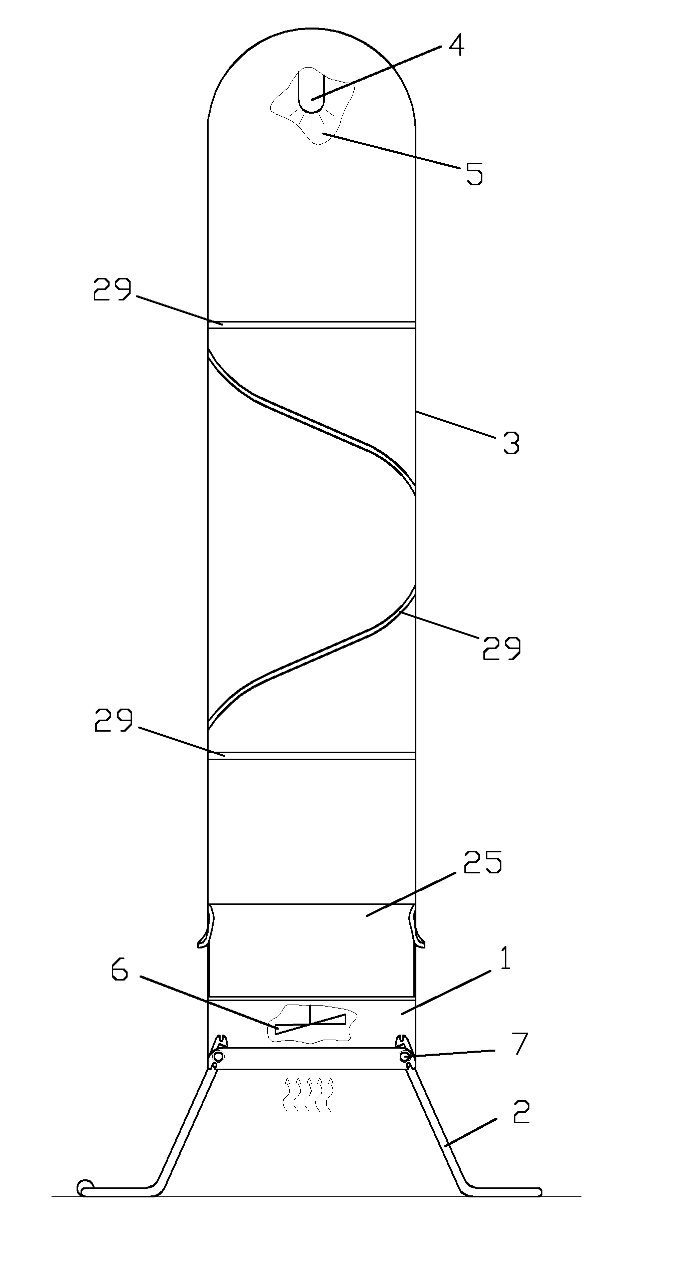
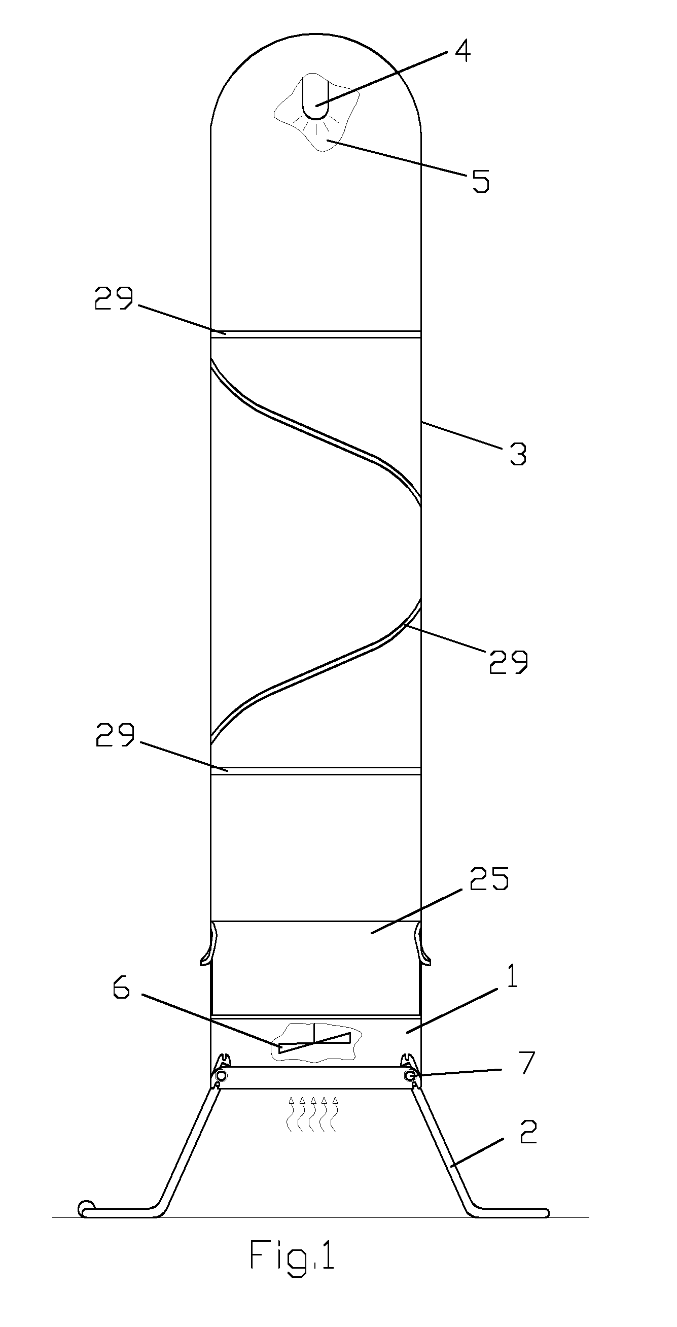
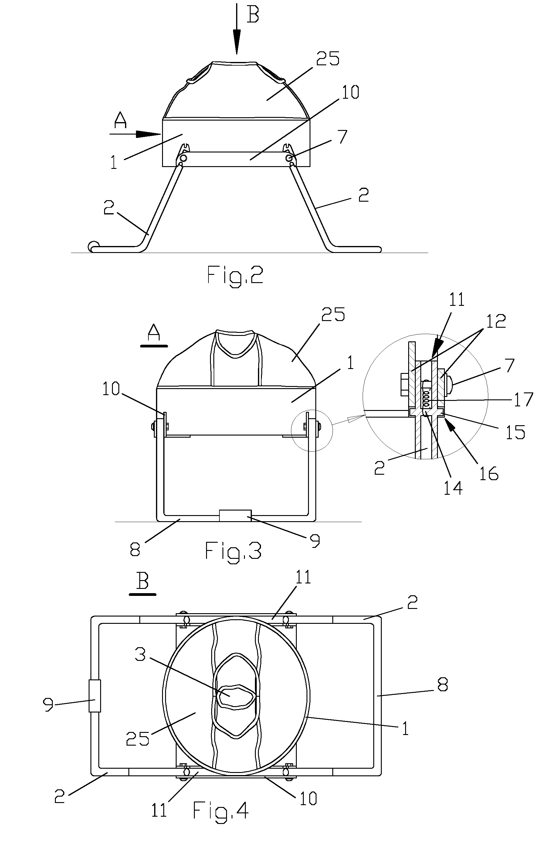
[0040]The inventive lighting installation (FIG. 1) comprises: a base 1 with supports 2; an inflatable shell 3 secured to the base 1, the shell 3 has an inner cavity 5; and an electric lamp 4 located inside the shell 3; wherein the lamp 4 is connected to a power supply (not shown), and wherein the inner cavity 5 (FIG. 1) is in communication with an air blower 6 installed in the base 1. The air blower 6 is in communication with atmosphere via an opening (not shown) provided in the base 1. The air blower 6 can be represented by a fan; the fan is typically connected to a rotation dr...


PUM


Abstract

The engineering solution relates to means for lighting a territory, mainly under emergency conditions. The solution allows for improving —reliability and stability of a lighting installation, and —convenience of carrying thereof and providing protection thereof during transportation. The lighting installation includes a base with supports, an inflatable shell secured to the base, and at least one electric lamp positioned inside the shell. The inner cavity of the shell is in communication with an air blower installed in the base. Each support has at least one hinge enabling turning the support and means for fixing the support. The solution contemplates a method for using the lighting installation, including mounting the installation on a power unit, before transforming thereof from a transportation position into an operative position. The place of power unit is adjusted to evenly distribute the installation's weight, the shell is inflated, the installation is secured to the power unit.

Description

CROSS-REFERENCE TO RELATED APPLICATIONS[0001]This application is a U.S. national stage application of a PCT application PCT / RU2011 / 000543 filed on 21 Jul. 2011, whose disclosure is incorporated herein in its entirety by reference, which PCT application claims priority of a EAPO patent application EA 201001107 filed on 22 Jul. 2010.FIELD OF THE INVENTION[0002]The present invention relates to means for illumination of a territory, mainly under emergency conditions. It is intended for use when electric power is off due to emergency or disaster as well as during construction works, repair, or search-and-rescue works in the nighttime.BACKGROUND OF THE INVENTION[0003]There are patent publications teaching inflatable lighting installations (U.S. Pat. No. 6,322,230B1, publ. 27.11.2001; RU 2192581C1, publ. 26.02.2001; RU 2286510C9, publ. 10.04.2006; WO 02 / 063207, publ. 15.08.2002), each of which has an elastic inflatable shell serving as a support for a light source secured inside the shell ...

Claims


Application Information

Patent Timeline
Patent Type & Authority Patents(United States)
IPC IPC(8): F21L13/00F21V3/02F21V17/00F21V21/06F21W131/10
CPCF21V3/023F21V17/007F21V21/06F21L13/00F21W2131/1005F21L14/00F21V21/406
Inventor NALITCHAEV, BORIS VLADIMIROVITCHNALITCHAEV, ILIA BORISOVITCH
Owner NALITCHAEV BORIS VLADIMIROVITCH
Why Eureka
Try Eureka