Light emitting device with spring-loaded LED-holder

a technology spring-loaded led-holders, which is applied in the direction of semiconductor devices for light sources, discharge tubes luminescnet screens, lighting and heating apparatus, etc. it can solve the problems of premature failure of led-based light-emitting devices, increased cost, and limited life of currently available led-based light-emitting devices. , to achieve the effect of improving mechanical fixation of at least one holding spring, less stress on solder, and low form

Active Publication Date: 2015-01-13
KONINK PHILIPS ELECTRONICS NV
View PDF13 Cites 105 Cited by
  • Summary
  • Abstract
  • Description
  • Claims
  • Application Information

AI Technical Summary

Benefits of technology

[0006]In view of the above-mentioned and other drawbacks of the prior art, a general object of the present invention is to provide an improved LED-based light-emitting device combining a long lifetime with the potential for low cost solutions.

Problems solved by technology

However, the lifetime of currently available LED-based light-emitting devices may sometimes be limited not by the LEDs themselves, but by other parts of the light-emitting device, such as the electrical connection between LED-module and circuit board.
Due to mismatch in the thermal expansion behavior of the LED-module and the PCB, temperature cycling may eventually result in defects in the solder connection between the LED-module and the PCB, which may lead to premature failure of the LED-based light-emitting device.
Although solving the lifetime problem, the replacement of the regular PCB by a ceramic-based circuit board results in a higher cost.
Furthermore, ceramic-based circuit boards are brittle, which may limit the form factor of the light-emitting device.

Method used


Image

  • Light emitting device with spring-loaded LED-holder
  • Light emitting device with spring-loaded LED-holder
  • Light emitting device with spring-loaded LED-holder

Examples


Embodiment Construction

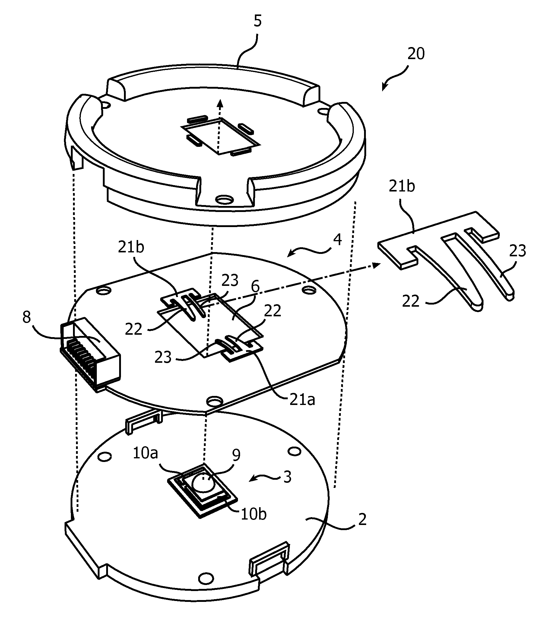
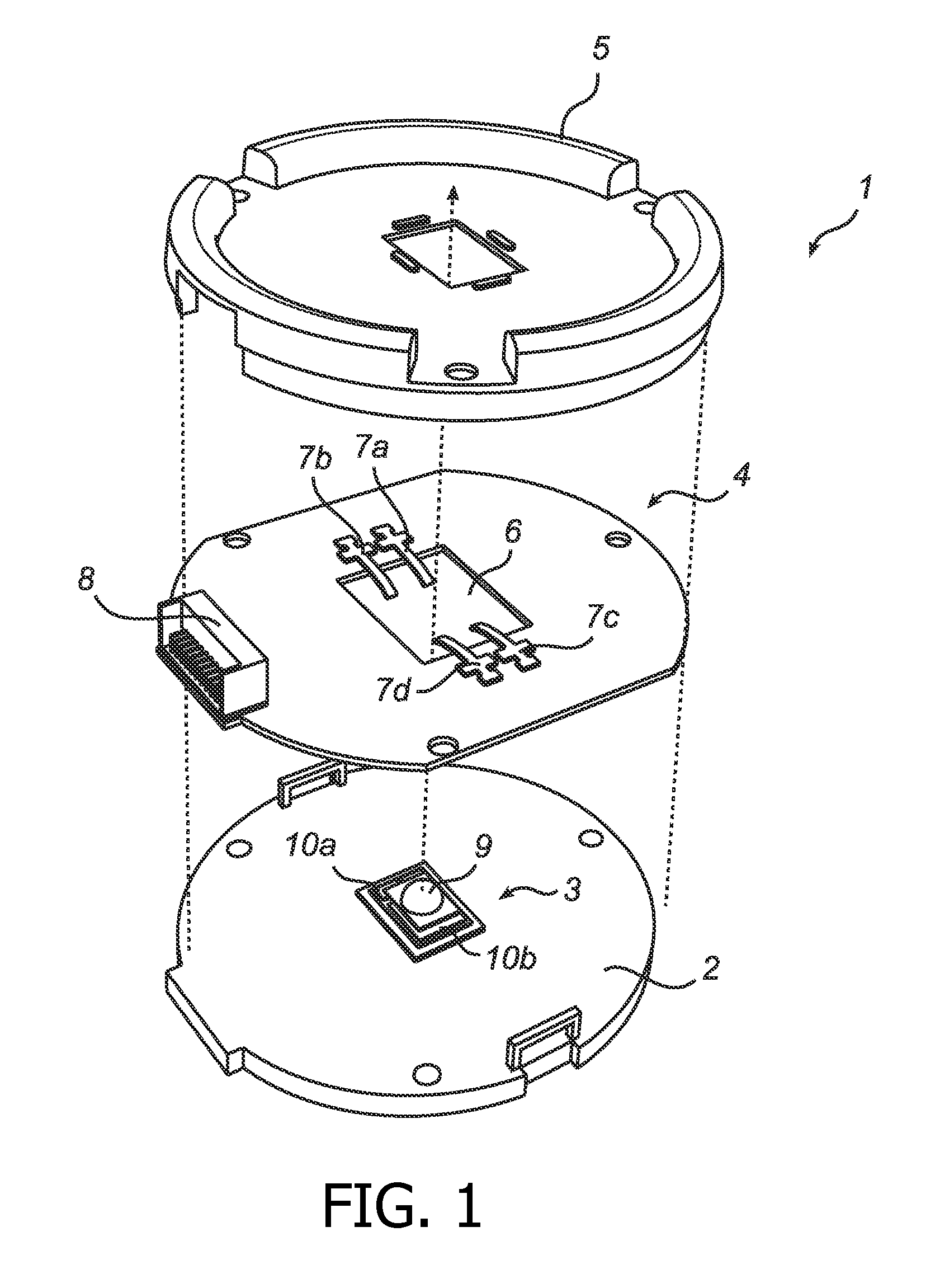
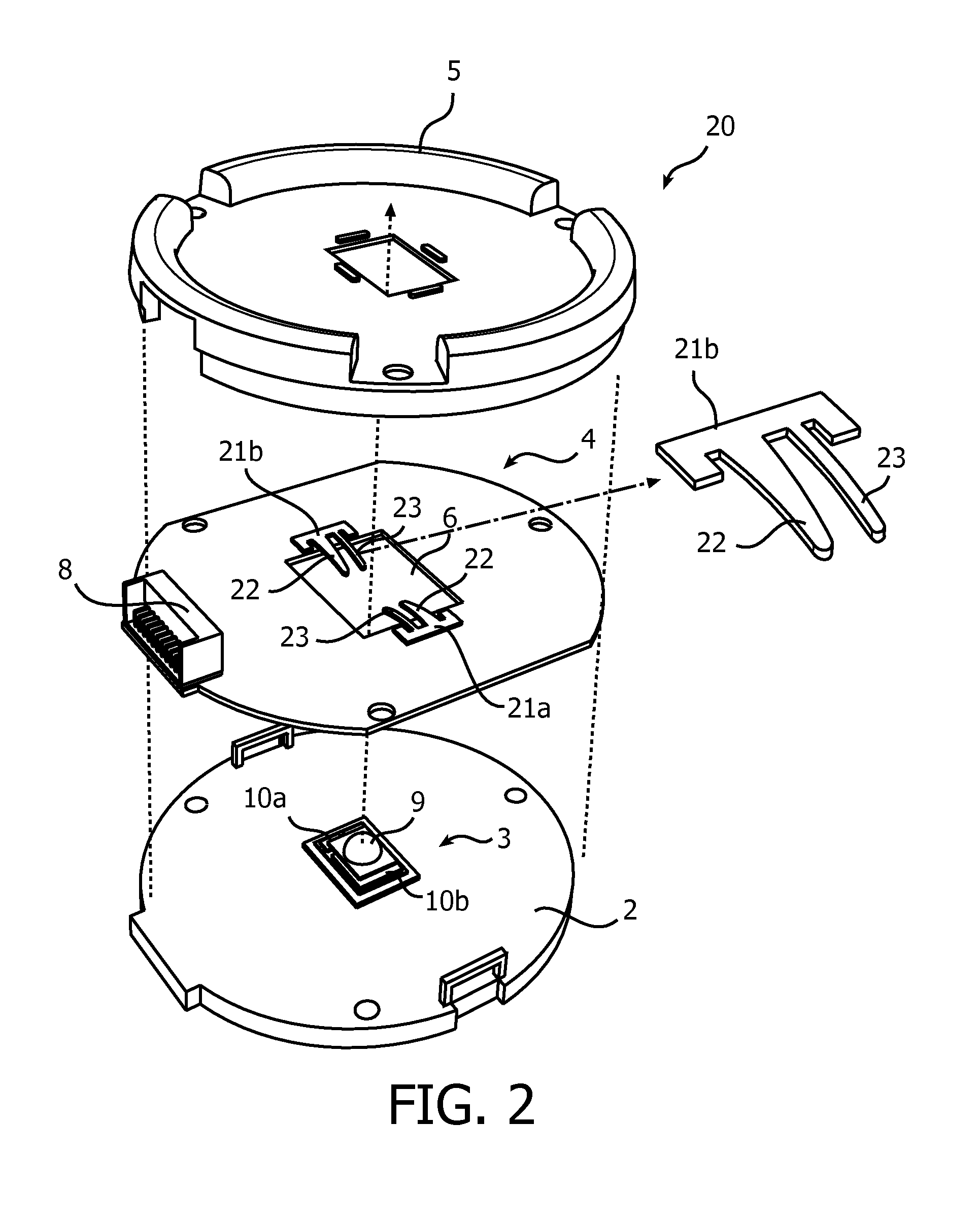
[0022]In the following description, the present invention is described with reference to a LED-based light-emitting device in which the connection board has a rectangular opening that completely surrounds the LED-module and sheet metal leaf springs are soldered to the connection board.

[0023]It should be noted that this by no means limits the scope of the invention, which is equally applicable to other light-emitting devices having an LED-holder that exerts a spring force to press the LED-module against the heat dissipator and an interconnecting member that allows movement between the connection pad(s) of the LED-module and the conductor pattern of the connection board. For example, other kinds of springs, such as one or several helical springs or plate springs, could be used to press the LED-module against the heat dissipator. Moreover, the interconnecting member may provide the desired relative lateral movement by other means, such as through a flexible wire that is electrically co...


PUM


Abstract

A light-emitting device (1), comprising an LED-module (3) comprising at least one LED mounted on a carrier and at least one connection pad (10a-b) for electrical connection of the LED module (3), a heat dissipator (2) for dissipating heat generated by the LED when in operation, a connection board (4) comprising a substrate having a conductor pattern for enabling provision of external power to the LED module (3), an interconnecting arrangement (7a-d) comprising at least one connection spring (7a-d) attached to the connection board (4) electrically interconnecting the at least one connection pad (10a-b) of the LED module (3) with the conductor pattern of the connection board (4), and an LED-holder comprising at least one holding spring (7a-d) attached to the connection board (4) exerting a spring force there by pressing the LED-module (3) against the heat dissipator (2) to provide a thermal connection between the LED-module (3) and the heat dissipator (2). The interconnecting arrangement (7a-d) is configured to allow movement between the conductor pattern of the connection board (4) and the at least one connection pad (10a-b). The at least one connection spring (7a-d) constitutes the at least one holding spring (7a-d), to simultaneously electrically interconnect the at least one connection pad (10a-b) of the LED-module (3) with the conductor pattern of the connection board (4) and press the LED-module (3) against the heat dissipator (2).

Description

CROSS-REFERENCE TO PRIOR APPLICATIONS[0001]This application is the U.S. National Phase application under 35 U.S.C. §371 of International Application No. PCT / IB2012 / 050681, filed on Feb. 15, 2012, which claims the benefit of EP11156862.2 filed on Mar. 3, 2011. These applications are hereby incorporated by reference herein.FIELD OF THE INVENTION[0002]The present invention relates to a LED-based light-emitting device.BACKGROUND OF THE INVENTION[0003]LED-based light-emitting devices are becoming more and more popular. One of the reasons for this popularity is the long lifetime of LEDs (light-emitting diodes). However, the lifetime of currently available LED-based light-emitting devices may sometimes be limited not by the LEDs themselves, but by other parts of the light-emitting device, such as the electrical connection between LED-module and circuit board.[0004]In currently available LED-based light-emitting devices, a LED-module is often soldered to a regular printed circuit board (PCB...

Claims


Application Information

Patent Timeline
Patent Type & Authority Patents(United States)
IPC IPC(8): H01L33/62H01L33/64F21V19/00F21V29/00F21Y101/02H05B33/02
CPCF21V19/001F21V29/004H05B33/02F21Y2101/02F21V29/20F21V29/246F21V29/89F21Y2115/10H05B33/06F21V29/00F21V19/00H01L33/64
Inventor KESER, MERIJNOEPTS, WOUTERVAN LIER, EDWIN PETRUS HELENAPETERS, RALPH HUBERT
Owner KONINK PHILIPS ELECTRONICS NV
Why Eureka
Try Eureka