
Wireless communication system, wireless communication method, and base station device

a wireless communication and wireless communication technology, applied in diversity/multi-antenna systems, site diversity, high-level techniques, etc., can solve the problems of deteriorating sinr, difficult to transmit information with a high throughput rate, and interference between downlink signals a and c, so as to achieve balanced transmission power of each antenna

Inactive Publication Date: 2015-01-13
HITACHI LTD
View PDF13 Cites 0 Cited by
  • Summary
  • Abstract
  • Description
  • Claims
  • Application Information

AI Technical Summary

Benefits of technology

The present invention provides a solution to the problem of concentrating power in specific antennas by allowing power to be evenly distributed among multiple antennas. This results in a more efficient use of resources and reduces the need for a costly and bulky base station device. The invention achieves a balance of transmission power among each antenna, preventing power from being concentrated in any one location, while still transmitting signals effectively. This allows for a more even distribution of power and better performance of the system.

Problems solved by technology

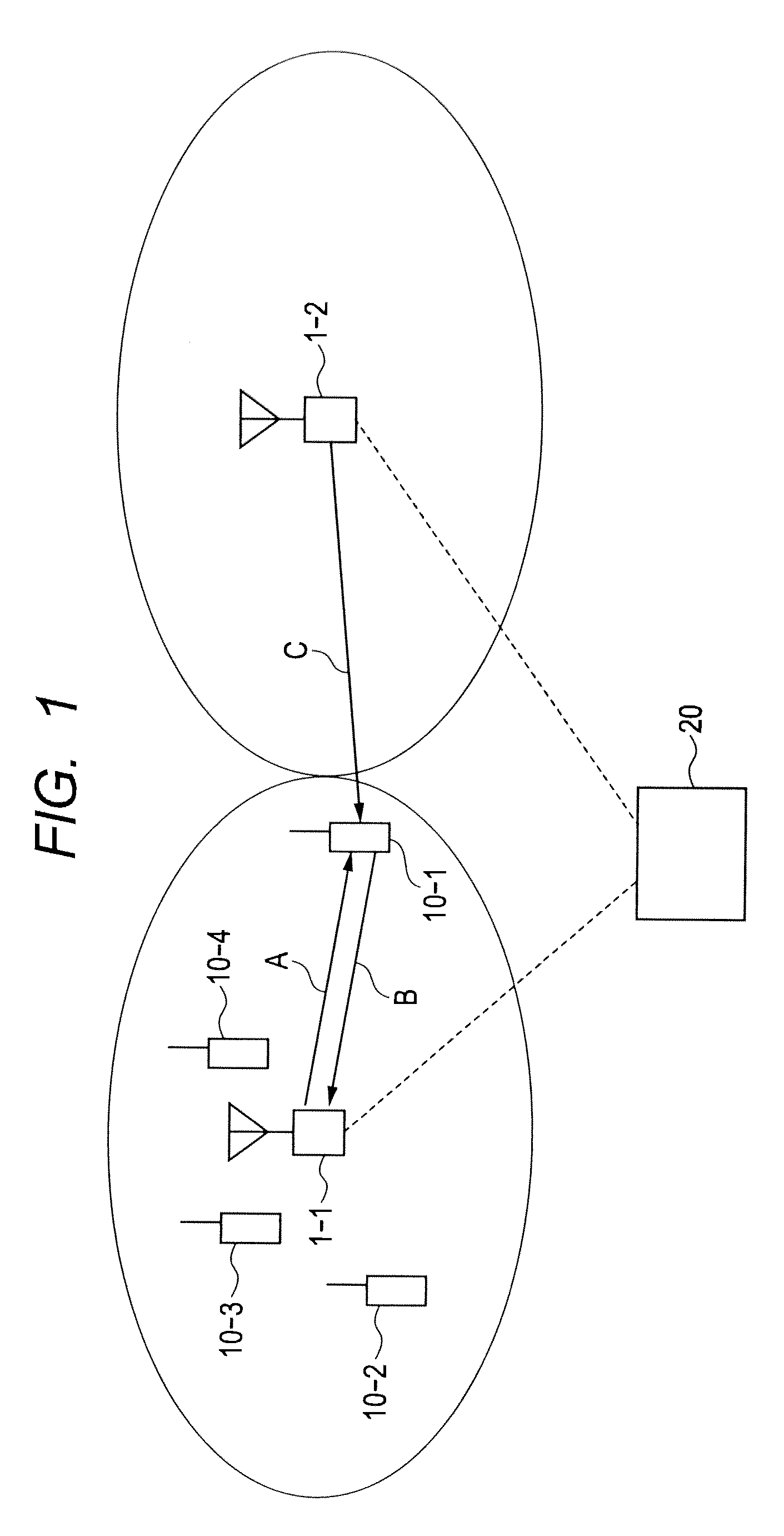
The base station 1-1 transmits the downlink signal A and the base station 1-2 transmits a downlink signal C. The base stations simultaneously transmit the signals at the same frequency and times, and thus there is a possibility that the downlink signals A and C interfere with each other.
Thus, the SINR is deteriorated and it is difficult to transmit information with a high throughput rate.
For example, even if transmission power is weakened in a specific frequency and a terminal that communicates using the frequency is located near a base station, affects of interference from the adjacent base station are small.
It has been impossible to individually change the transmission power of sub-bands between antennas.

Method used


Image

  • Wireless communication system, wireless communication method, and base station device
  • Wireless communication system, wireless communication method, and base station device
  • Wireless communication system, wireless communication method, and base station device

Examples


first embodiment

[0041]It has been proposed in the fourth generation communications that the number of antennas of each of base stations and terminals is four or more. Regarding LIE-Advanced and IEEE802.16m, it has been discussed that each base station is provided with up to eight antennas and each terminal is provided with four antennas. However, signals are transmitted using two antennas in standard and basic operations.

[0042]In view of the foregoing, in the case where signals are basically transmitted using two antennas, plural antennas and frequency bands are effectively used to avoid concentration of power on specific antennas and to equalize transmission power between antennas in the first embodiment.

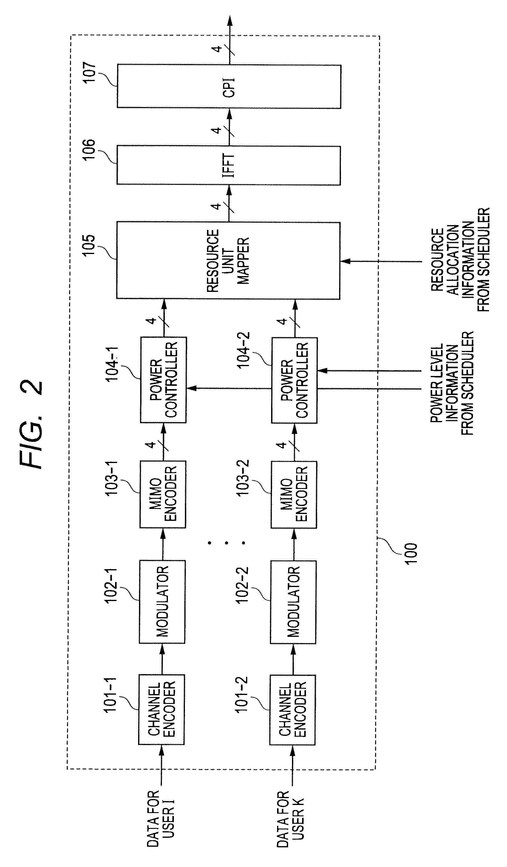
[0043]With reference to FIG. 5, a base station device will be described. In FIG. 5, abase station device 1 includes antennas 201, a Radio Frequency (RF) 202, a baseband signal processor 203, a CPU 204, a Network (NW) I / F 205, and a memory 206. The CPU 204 includes a scheduler 2041.

[0044]The NW I / F...

second embodiment

[0077]With reference to FIG. 12, operations of transmission power allocation / frequency resource allocation of a scheduler 2041 according to a second embodiment will be described. It should be noted that the configuration and the transmission signal process of the base station device in the second embodiment are the same as those in the first embodiment.

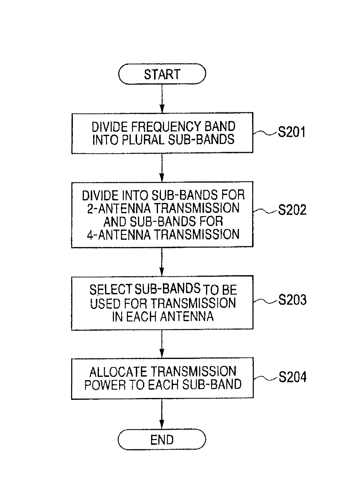
[0078]In FIG. 12, Step 201 and Step 202 are the same as Step 101 and Step 102 in FIG. 8.

[0079]Next, the scheduler 2041 selects sub-bands used for transmission belonging to 2-antenna transmission in each antenna (S203). Specifically, the scheduler 2041 selects sub-bands belonging to the lower half of frequencies among the areas where 2-antenna transmission is performed in the antennas 0 and 1, and selects sub-bands belonging to the other half in the antennas 2 and 3, so that sub-bands used for each antenna are determined. In each antenna, signals are not transmitted in the sub-bands that are not selected, and power allocation (to be de...


PUM


Abstract

In a cellular wireless communication system with plural antenna base stations, signals have been basically transmitted using two antennas among plural antennas, and thus power has been concentrated in specific antennas. The present invention controls the transmission power of each antenna so as not to increase the transmission power of specific antennas by effectively using plural antennas and frequency bands. A frequency band is divided into plural sub-bands, and antennas used for transmission are spread to the sub-bands. In each sub-band, power is not allocated to an antenna that is not used for transmission. As a result, the transmission power of each antenna can be balanced, and power can be prevented from being concentrated in specific antennas.

Description

CLAIM OF PRIORITY[0001]The present application claims priority from Japanese patent application serial no. 2011-098583, filed on Apr. 26, 2011, the content of which is hereby incorporated by reference into this application.BACKGROUND OF THE INVENTION[0002]The present invention relates to a wireless communication system, a wireless communication method, and a base station device, and particularly to a wireless communication system, a wireless communication method, and a base station device for controlling transmission power or allocating channels in an antenna-rich base station of a cellular wireless communication system.1. Cellular Wireless Communication System[0003]In mobile wireless communications, a cellular communication system is common because communications are performed in service areas expanding as planes. In the cellular communication system, plural base stations are scattered in service areas, and areas (where terminals can communicate) covered by the respective base stat...

Claims


Application Information

Patent Timeline
Patent Type & Authority Patents(United States)
IPC IPC(8): H04B7/00H04B7/02H04B7/04H04B7/06
CPCH04B7/024H04B7/0465H04B7/0691Y02D30/70
Inventor ADACHI, HIROTO
Owner HITACHI LTD
Learn More