Tape servo track write compensation

a servo track and write compensation technology, applied in the field of magnetic information storage and retrieval, can solve the problems of shrinking or expanding the lateral spacing of the data tracks in the data band, the inability to accurately align the tape head to the data and servo track, and the inability to maintain the head carrier alignmen

Inactive Publication Date: 2015-01-20
GLOBALFOUNDRIES INC
View PDF15 Cites 15 Cited by
  • Summary
  • Abstract
  • Description
  • Claims
  • Application Information

AI Technical Summary

Problems solved by technology

As densities for linear tape storage systems increase due to advancements in materials and storage schemes, precision alignment of the tape heads to data and servo tracks is an increasingly challenging requirement for accurate recording and reading of stored data.
At high track densities, alignment is affected by changes in tape width due to environmental conditions, such as temperature and humidity, and mechanical stress to the tape, which can cause the lateral spacing of the data tracks in a data band to shrink or expand.
Generally, increasing the temperature or humidity will cause expansion of the tape width, and applying longitudinal stress to the tape will cause tension narrowing of the tape width.
Changes to the lateral spacing of the data and servo tracks may result in a misalignment of the tape head elements on the tape head assembly, such as read and write heads, with the data and servo tracks on the tape.
Further variation may be introduced by tolerances in constructing the servo writer head, which will also lead to differences in servo pattern spacing.
Additionally, aging of the tape causes the servo pattern spacing to change over time.
This change is typically non-uniform due to the differences in pack pressure, or how tightly wound the tape is, within the tape cartridge.

Method used


Image

  • Tape servo track write compensation
  • Tape servo track write compensation
  • Tape servo track write compensation

Examples


Embodiment Construction

[0018]The following description is made for the purpose of illustrating the general principles of the present invention and is not meant to limit the inventive concepts claimed herein. Further, particular features described herein can be used in combination with other described features in each of the various possible combinations and permutations.

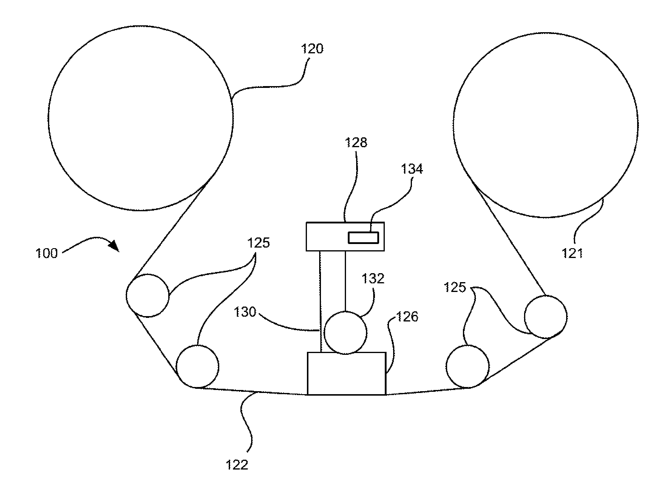
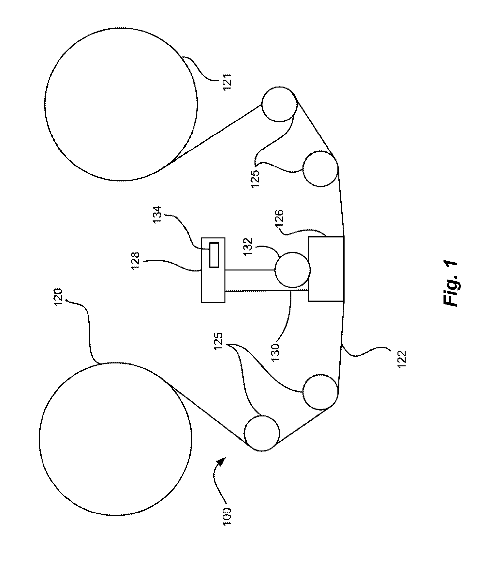
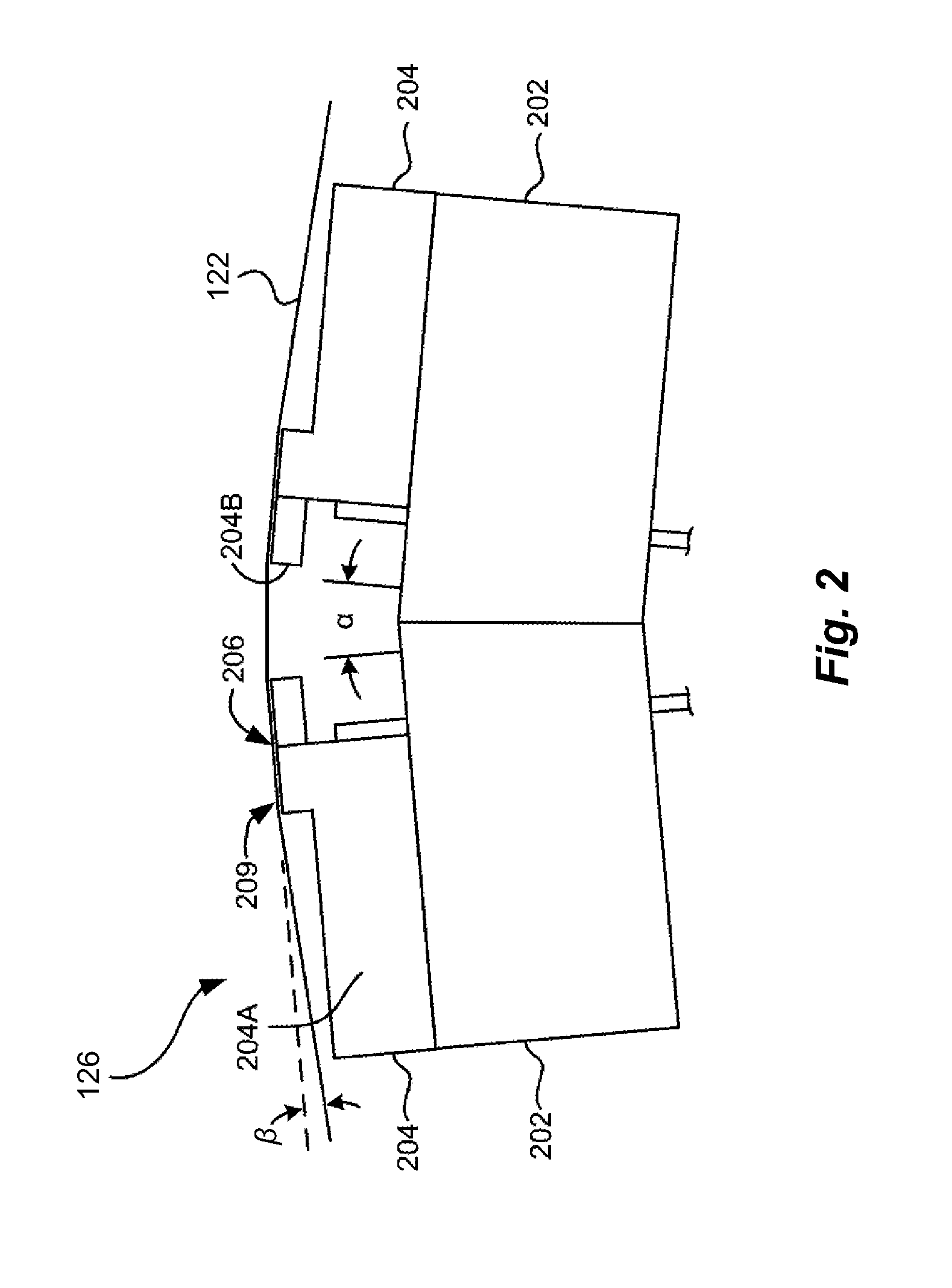
[0019]An embodiment of the present invention generally describes a method and apparatus for setting the spacing of servo write heads such that there is a nominal lateral spacing between the servo tracks at the nominal operating temperature and humidity associated with the nominal spacing. Coefficients of thermal and hygroscopic expansion for the tape and tape head substrate materials, and the manufacturing environment temperature and humidity, may be used to determine the servo write head spacing during manufacturing such that at the nominal temperature and humidity, the servo track spacing will be at the nominal value. The nominal servo t...


PUM

PropertyMeasurementUnit
coefficient of thermal expansionaaaaaaaaaa
coefficient of hygroscopic expansionaaaaaaaaaa
data structureaaaaaaaaaa

Abstract

Setting a servo write head spacing for writing servo tracks on a magnetic tape in a manufacturing environment. One or more processors receive one or more environmental condition measurements of the manufacturing environment. The processors determine a spacing for a pair of servo write heads based at least on a nominal spacing for the pair of servo tracks, and a product of a difference between the nominal environmental conditions associated with the nominal spacing and the corresponding environmental condition measurements of the manufacturing environment, and coefficients of expansion for the magnetic tape. Spacing for the pair of servo write heads is set to the determined spacing, such that the spacing of the pair of servo write heads is substantially the nominal spacing when the one or more manufacturing environment environmental condition measurements are the one or more nominal environmental conditions.

Description

FIELD OF THE INVENTION[0001]The present invention relates generally to the field of magnetic information storage and retrieval, and more particularly to automatically compensating for manufacturing environmental changes when writing servo patterns to magnetic tape.BACKGROUND OF THE INVENTION[0002]As densities for linear tape storage systems increase due to advancements in materials and storage schemes, precision alignment of the tape heads to data and servo tracks is an increasingly challenging requirement for accurate recording and reading of stored data. At high track densities, alignment is affected by changes in tape width due to environmental conditions, such as temperature and humidity, and mechanical stress to the tape, which can cause the lateral spacing of the data tracks in a data band to shrink or expand. Generally, increasing the temperature or humidity will cause expansion of the tape width, and applying longitudinal stress to the tape will cause tension narrowing of th...

Claims


Application Information

Patent Timeline
Patent Type & Authority Patents(United States)
IPC IPC(8): G11B5/584
CPCG11B5/584G11B5/4893G11B20/1201
Inventor HERGET, PHILIPP
Owner GLOBALFOUNDRIES INC
Why Eureka
Try Eureka