
Automatic capture of diagnostic data based on transaction behavior learning

a technology of transaction behavior and diagnostic data, applied in the field of automatic capture of diagnostic data based on transaction behavior learning, can solve the problems of inability to collect additional information, difficult to track and monitor the topology of the machines that provide the service, and inability to track the performance of the web servi

Active Publication Date: 2015-01-20
CISCO TECH INC
View PDF154 Cites 33 Cited by
  • Summary
  • Abstract
  • Description
  • Claims
  • Application Information

AI Technical Summary

Benefits of technology

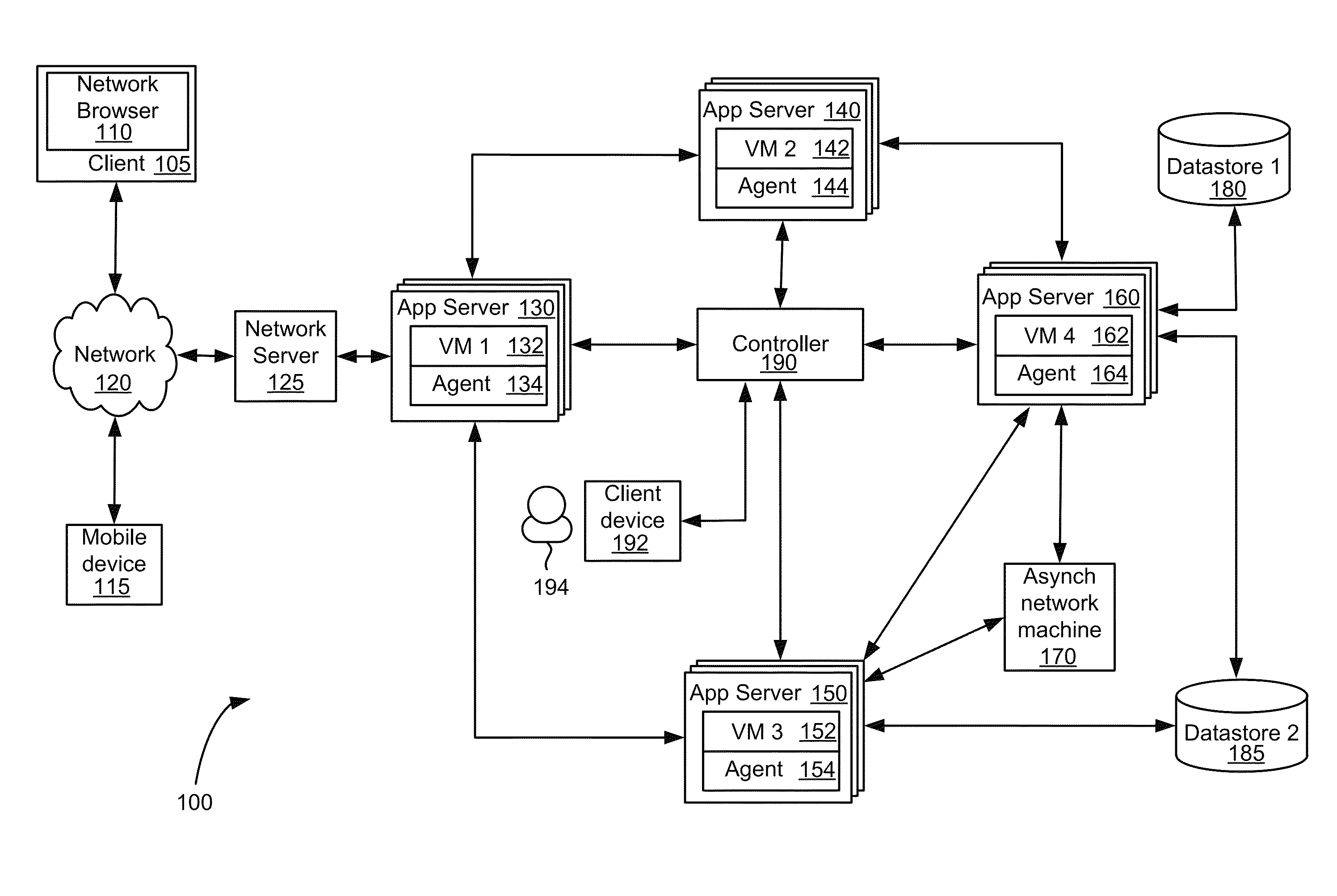
The present technology monitors a distributed network application system and can detect abnormal behavior based on the learned behavior of the system. It automatically collects diagnostic data for business transactions and requests based on learned behavior, which includes detailed data for operation of distributed web applications. This data is processed to identify performance issues for transactions. Agents monitoring the transactions collect the data, which is reported to central controllers, who assemble the data and identify abnormalities. The technology allows for monitoring of individual requests, history of requests, and baselines for performance. Overall, the technology facilitates detection and troubleshooting of abnormal behavior in distributed network application systems.

Problems solved by technology

The applications may be distributed over several machines, making the topology of the machines that provides the service more difficult to track and monitor.
When a web application is distributed over several machines, tracking the performance of the web service can become impractical with large amounts of data collected from each machine.
Collecting the additional information can consume large amounts of resources and often requires significant time to determine how to collect the information.

Method used


Image

  • Automatic capture of diagnostic data based on transaction behavior learning
  • Automatic capture of diagnostic data based on transaction behavior learning
  • Automatic capture of diagnostic data based on transaction behavior learning

Examples


Embodiment Construction

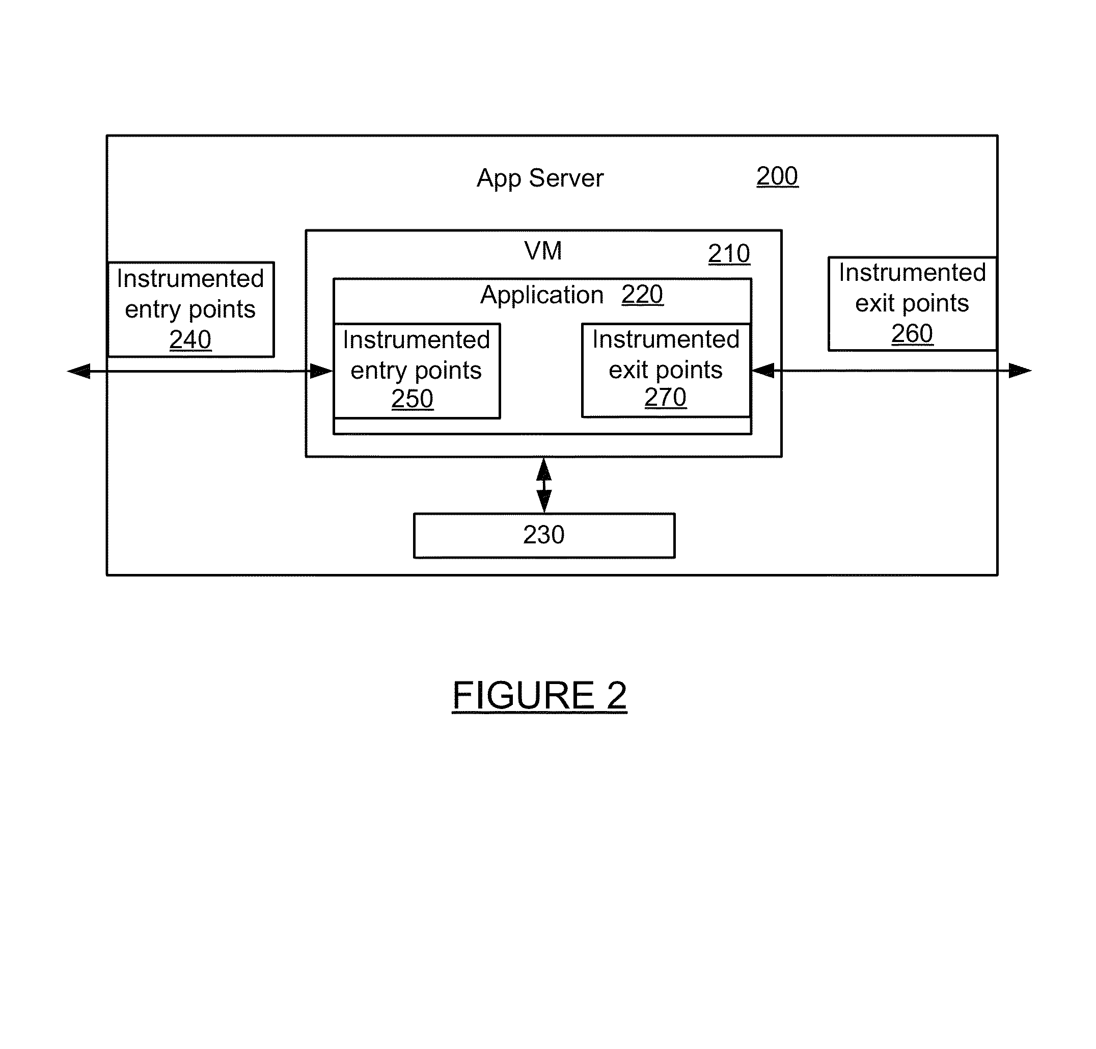
[0025]The present technology monitors a network or web application provided by one or more distributed applications. The web application may be provided by one or more web services each implemented as a virtual machine or one or more applications implemented on a virtual machine. Agents may be installed on one or more servers at an application level, virtual machine level, or other level. An agent may monitor a corresponding application (or virtual machine) and application communications. Each agent may communicate with a controller and provide monitoring data to the controller. The controller may process the data to learn and evaluate the performance of the application or virtual machine, model the flow of the application, and determine information regarding the distributed web application performance. The monitoring technology determines how each distributed web application portion is operating, establishes a baseline for operation, and determines the architecture of the distribut...


PUM


Abstract

The present technology may determine an anomaly in a portion of a distributed business application. Data can automatically be captured and analyzed for the portion of the application associated with the anomaly. By automatically capturing data for just the portion associated with the anomaly, the present technology reduces the resource and time requirements associated with other code-based solutions for monitoring transactions. A distributed business application is monitored to detect an anomaly based the learned behavior of the business application. The behavior may be learned for each of one or more machines which implement a distributed business transaction. The present system may automatically collect diagnostic data for one or more business transactions and / or requests based on learned behavior for the business transaction or request. Data for a distributed business application transaction may be collected by sampling one or more threads assigned to handle portions of the distributed business transaction. Data regarding the distributed transaction may then be reported from agents monitoring portions of the distributed transaction to one or more controllers and assembled by one or more controllers into business transactions.

Description

CROSS-REFERENCE TO RELATED APPLICATIONS[0001]This application is a continuation-in-part and claims the priority benefit of U.S. patent application Ser. No. 12 / 878,919, titled “Monitoring Distributed Web Application Transactions,” filed Sep. 9, 2010, which claims the priority benefit of U.S. Provisional Application Ser. No. 61 / 241,256, titled “Automated Monitoring of Business Transactions,” filed Sep. 10, 2009, the disclosure of which is incorporated herein by reference.BACKGROUND OF THE INVENTION[0002]The World Wide Web has expanded to provide web services faster to consumers. Web services may be provided by a web application which uses one or more services to handle a transaction. The applications may be distributed over several machines, making the topology of the machines that provides the service more difficult to track and monitor.[0003]Monitoring a web application helps to provide insight regarding bottle necks in communication, communication failures and other information reg...

Claims


Application Information

Patent Timeline
Patent Type & Authority Patents(United States)
IPC IPC(8): G06F15/173
CPCH04L43/04H04L43/022H04L67/22H04L43/045H04L67/02H04L43/10H04L67/535H04L43/16
Inventor BANSAL, JYOTISUNKARA, BHASKAR
Owner CISCO TECH INC
Learn More