Analyzing diagnostic data generated by multiple threads within an instruction stream

a diagnostic data and instruction stream technology, applied in the field of data processing, can solve the problems of not allowing the diagnosis of a significant part of the program, difficult for a programmer to understand the view of the program execution derived from the diagnostic mechanism such as debugging, and difficult to relate back to the original sequential program

Inactive Publication Date: 2008-04-24
ARM LTD
View PDF0 Cites 110 Cited by
  • Summary
  • Abstract
  • Description
  • Claims
  • Application Information

AI Technical Summary

Benefits of technology

[0065]As previously mentioned, when compiling a computer program to be processed by a plurality of processing units decisions on how the program is divided and which bits are sent to which processor are made. Thus, if additional information regarding this process can

Problems solved by technology

However, a drawback of this is that the view of the program execution derived from diagnostic mechanisms such as debug are difficult for a programmer to understand and to relate back to the original sequential program.
Clearly this has the disadvantage of not allowing diagnosis of a significant part of the program.
In summary, when multiple processors are executing in parallel and independently producing traces of diagnostic information, it can be hard to understand the resulting traces independently of each other.
While this approach does significantly simplify the event stream, it leaves a significant semantic gap between the program as written by the programmer and the program as executed on the multi-processor system.
This makes debugging the system harder because the programmer must disregard the order of some events (e.g., exactly when does T3 run) while paying careful attention to other events (e.g., that T1 and T2 execute in sequence).
The problem identified above comes from the topological sort making sorting decisions based only on how the hardware runs the output of the transforming compiler.
Furthermore,

Method used


Image

  • Analyzing diagnostic data generated by multiple threads within an instruction stream
  • Analyzing diagnostic data generated by multiple threads within an instruction stream
  • Analyzing diagnostic data generated by multiple threads within an instruction stream

Examples


Embodiment Construction

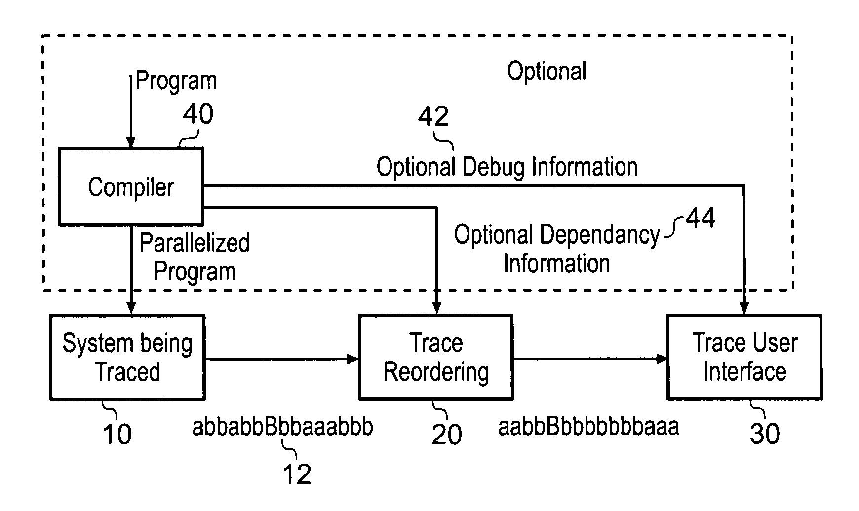
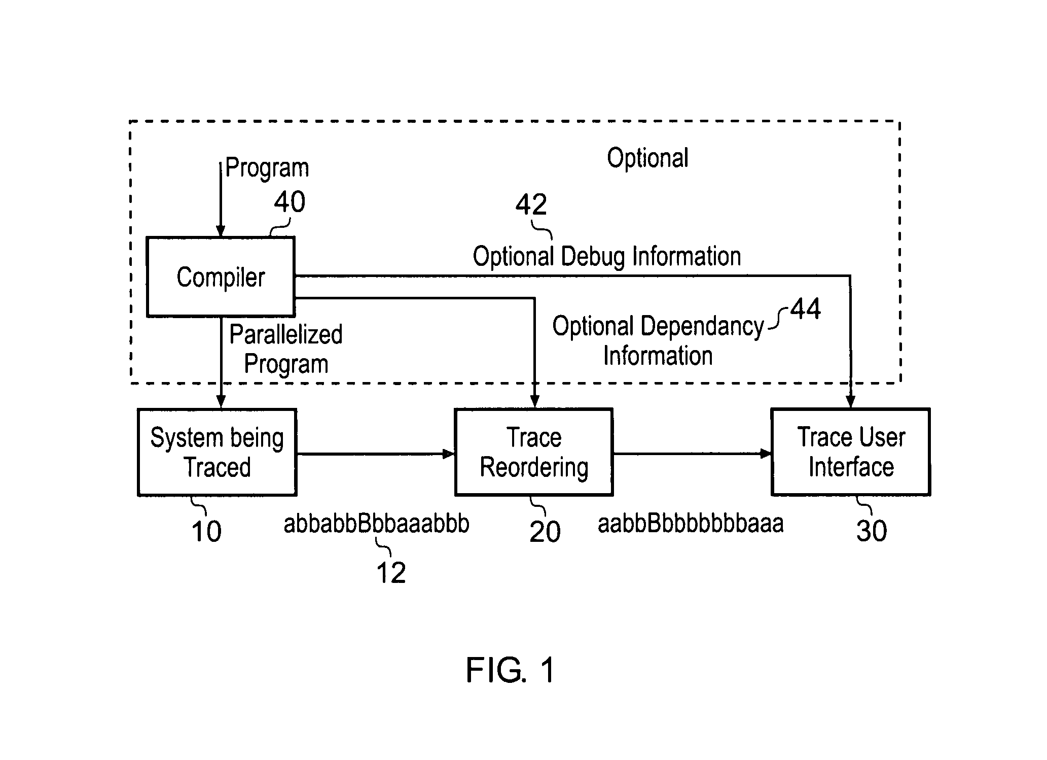
[0091]FIG. 1 shows very schematically an embodiment of the present invention. This embodiment comprises a system 10 which is a multi-threaded program running on a multiprocessor system. When this system is being traced, a stream of trace data 12 which consists of a complex sequence of events of all the different threads and processes in the system is produced. This trace data is very hard to analyse and thus, the invention uses trace reordering logic 20 to reorder this trace into an order which more closely resembles the order of the original program and as such is easier to understand by a programmer. This reorder data is then input to trace user interface 30.

[0092]The trace reordering logic can reorder the trace data in a number of ways. In the embodiments shown, the complex sequence of events that are output from the system being traced comprise synchronisation events which are indicated as capitals in the stream of data 12. These synchronisation events are events where one proce...


PUM


Abstract

A diagnostic method for outputting diagnostic data relating to processing of instruction streams stemming from a computer program, at least some of said instructions streams comprising multiple threads is disclosed. The method comprises the steps of: (i) receiving diagnostic data; (ii) reordering said received diagnostic data in dependence upon reordering data, said reordering data comprising data relating to said computer program; and (iii) outputting said reordered diagnostic data. In general, the instructions streams are processed by a plurality of processing units arranged to process at least some of said instructions in parallel, said diagnostic data being received from said plurality of processing units.

Description

BACKGROUND OF THE INVENTION[0001]1. Field of the Invention[0002]The present invention relates to the field of data processing and in particular to diagnostic mechanisms for monitoring data processing operations.[0003]2. Description of the Prior Art[0004]Systems are being developed that have multiple processing units operable to process data in parallel. A compiler will compile a program to execute on a particular hardware system such that in a multi-processor system portions of the program will be sent to be executed by different processing units. Thus, much of the program will be executed in parallel and executing times and processing performance will be improved. However, a drawback of this is that the view of the program execution derived from diagnostic mechanisms such as debug are difficult for a programmer to understand and to relate back to the original sequential program.[0005]When an application has been split into multiple threads automatically, there are two conventional ...

Claims


Application Information

Patent Timeline
IPC IPC(8): G06F9/44
CPCG06F11/3636G06F11/362G06F11/36G06F11/3466G06F11/28G06F11/22
Inventor REID, ALASTAIR DAVIDFORD, SIMON ANDREWKNEEBONE, KATHERINE ELIZABETH
Owner ARM LTD
Why Eureka
Try Eureka