
Parallel passage fluid contactor structure

a fluid contactor and parallel passage technology, applied in the direction of catalyst activation/preparation, chemical/physical/physicochemical stationary reactors, metal/metal-oxide/metal-hydroxide catalysts, etc., can solve the problems of poor thermal characteristics of the structure, shortcoming of certain parallel passage fluid contactor structures, undetectable large temperature differences

Active Publication Date: 2015-01-27
INVENTYS THERMAL TECH
View PDF134 Cites 21 Cited by
  • Summary
  • Abstract
  • Description
  • Claims
  • Application Information

AI Technical Summary

Problems solved by technology

However, a shortcoming of certain of the parallel passage fluid contactor structures of the prior art relates to poor thermal characteristics of the structure.
In particular, prior art parallel passage fluid contactors may have undesirably high thermal mass which may require an undesirably large thermal energy flux to effect a given temperature change in the structure, or may have undesirably low thermal conductivity which may result in undesirably large temperature differences within the structure, for example.
Such undesirable thermal characteristics of certain parallel passage fluid contactors of the prior art may result in increased costs related to thermal regeneration of fluid contactors, and / or limited efficiency of chemical separations or reactions within the fluid contactors of the prior art.

Method used


Image

  • Parallel passage fluid contactor structure
  • Parallel passage fluid contactor structure
  • Parallel passage fluid contactor structure

Examples


Embodiment Construction

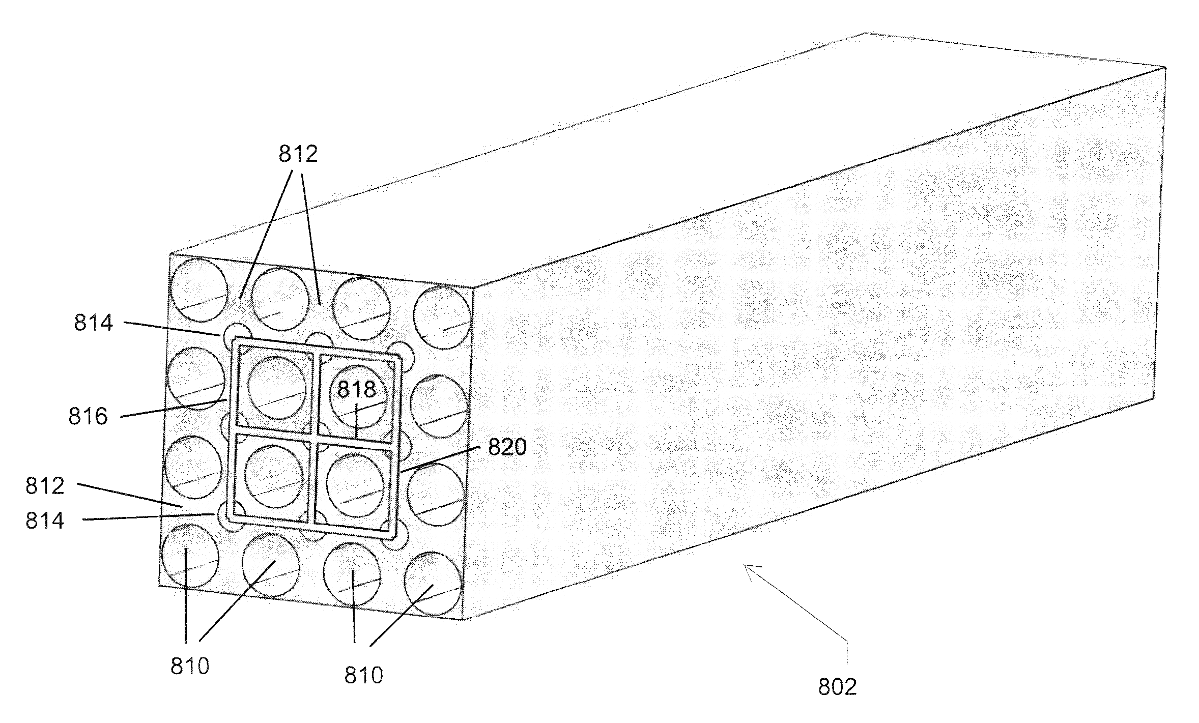
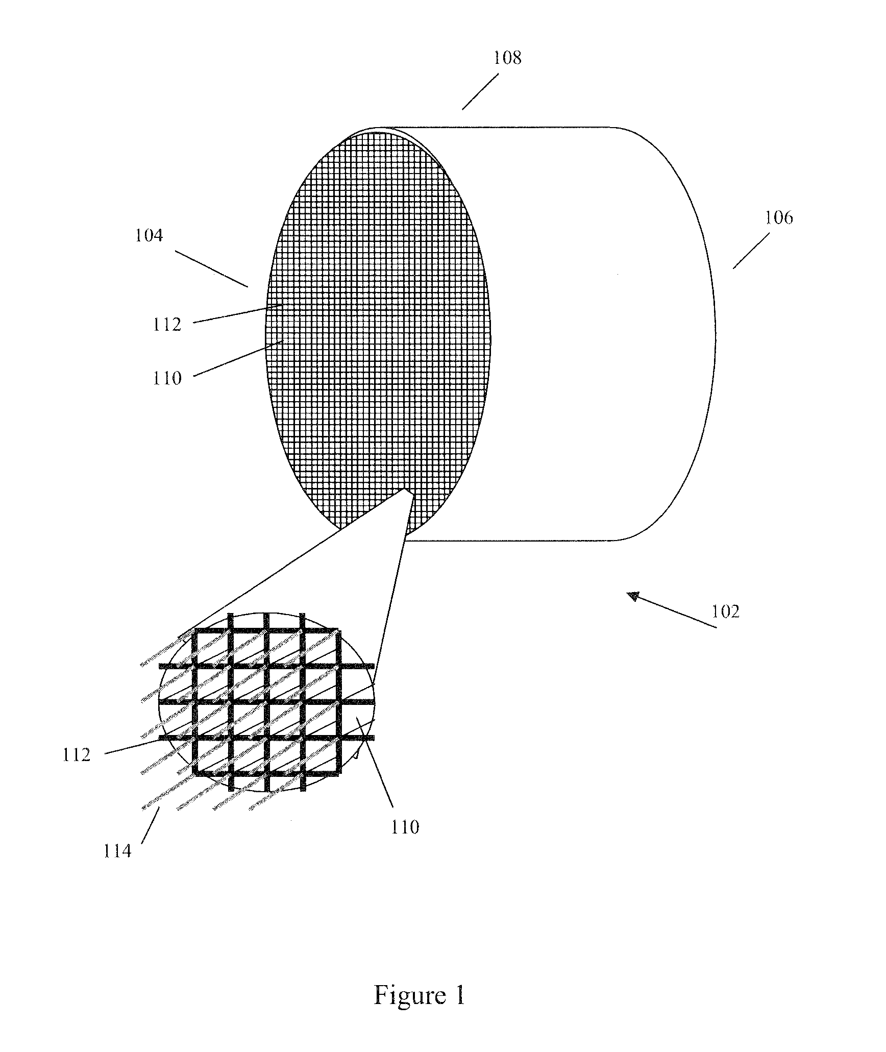
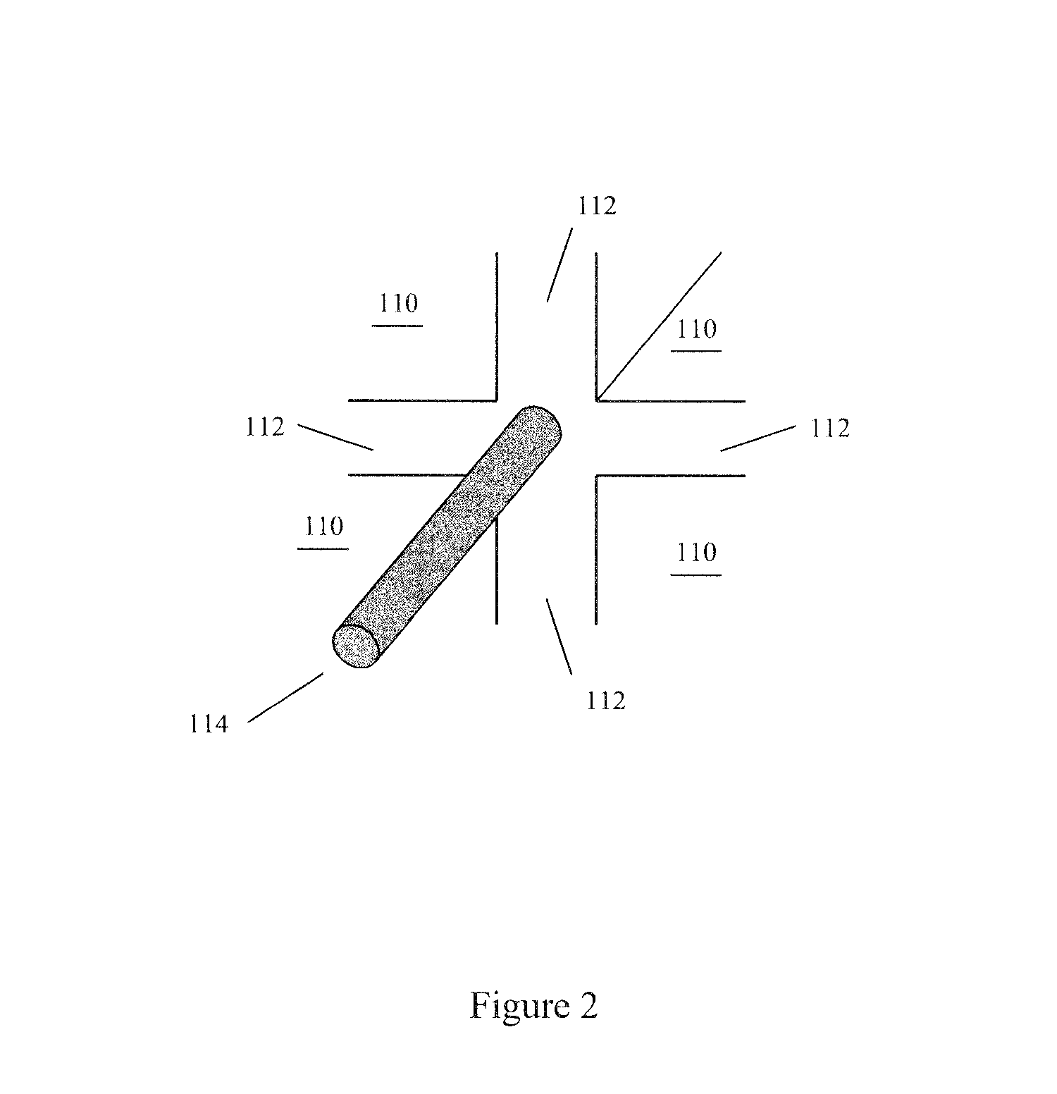
[0027]FIG. 1 illustrates an exemplary parallel passage fluid contactor structure according to an embodiment of the invention. The exemplary parallel passage fluid contactor structure indicated generally at 102 comprises a substantially cylindrical shape defined by substantially cylindrical outer surface 108. The exemplary structure 102 is shown with first and second ends 104 and 106, with multiple substantially parallel passages 110 extending axially along the length of the structure 102, from the first end 104 to the second end 106. The parallel passages 110 are preferably continuous along the length of the structure 102 and are adapted to allow the flow of fluid through the passages 110. Parallel passages 110 are separated from each other by cell walls 112 to form an exemplary honeycomb structure wherein each passage 110 is substantially separated from adjacent passages 110 by at least one cell wall 112. Parallel passage contactor structure 102 also comprises axially continuous co...


PUM

PropertyMeasurementUnit
thermal energyaaaaaaaaaa
cross-sectional shapeaaaaaaaaaa
conductiveaaaaaaaaaa

Abstract

A parallel passage fluid contactor structure for chemical reaction processes has one or more segments, where each segment has a plurality of substantially parallel fluid flow passages oriented in an axial direction; cell walls between each adjacent fluid flow passages and each cell wall has at least two opposite cell wall surfaces. The structure also includes at least one active compound in the cell walls and multiple axially continuous conductive filaments either embedded within the cell walls or situated between the cell wall surfaces. The conductive filaments are at least one of thermally and electrically conductive, are oriented in axially, and are in direct contact with the active compound, and are operable to transfer thermal energy between the active material and the conductive filaments. Heating of the conductive filaments may be used to transfer heat to the active material in the cell walls. Methods of manufacturing the structure are discussed.

Description

1. TECHNICAL FIELD[0001]The present invention relates generally to parallel passage fluid contactor structures. More particularly, the present invention relates to a thermally conductive parallel passage fluid contactor structure and method for its manufacture.2. BACKGROUND OF THE INVENTION[0002]Fluid contactor structures are known in the art for use in chemical processes requiring intimate contact of fluids with an active compound, such as adsorption or catalysis processes for example. Exemplary known fluid contactor structures include ceramic honeycomb structures for exhaust gas catalysis, and packed bead or parallel plate adsorbent structures for adsorptive gas separation processes such as thermal and / or pressure swing adsorption processes. However, a shortcoming of certain of the parallel passage fluid contactor structures of the prior art relates to poor thermal characteristics of the structure. In particular, prior art parallel passage fluid contactors may have undesirably hig...

Claims


Application Information

Patent Timeline
Patent Type & Authority Patents(United States)
IPC IPC(8): B01D39/06B01D39/20B01D39/14B01D24/00B01D50/00B01D53/04B01J12/00B01J19/24C04B38/00C04B111/00C04B111/94F28D9/04F28F3/02F28F7/02
CPCB01D53/0462B01J12/007B01J19/2485C04B38/0006C04B38/0083H05B3/50F28D9/04F28F3/025F28F7/02H05B2203/021B01D2253/102B01D2253/104B01D2253/108B01D2253/204B01J2219/0004B01J2219/00135C04B2111/00379C04B2111/0081C04B2111/94H05B2203/022H05B2203/024B01J20/28045Y10T428/24132Y10T428/24074B01J20/3007B01J20/3291C04B35/80C04B35/83C04B38/0016B01D53/0407B01D2253/1124B01D2253/116B01D2253/202B01J35/04B01J37/0201
Inventor BOULET, ANDREKHIAVI, SOHEIL
Owner INVENTYS THERMAL TECH
Learn More