Terminal fitting and method of producing it

a technology of terminal fittings and fittings, applied in the direction of coupling contact members, coupling device connections, electrical devices, etc., can solve the problems of limited number of terminal fittings, and affecting the operation of the terminal fittings

Inactive Publication Date: 2015-02-03
SUMITOMO WIRING SYST LTD
View PDF16 Cites 8 Cited by
  • Summary
  • Abstract
  • Description
  • Claims
  • Application Information

AI Technical Summary

Benefits of technology

[0011]The contact portion is formed by striking, hammering, embossing or deforming the ceiling plate to project from the inner surface of the ceiling plate by more than the plate thickness. The struck or bent portion is at the same height as or below where the contact portion is formed, which allows outer surface of the pressing portion to be at the same height as or below the ceiling plate rather than projecting outwardly, which allows the height of the terminal fitting to be reduced. In addition, because the plate thickness of the struck or bent portion is maintained there is no actual pressing by the pressing portion and no corresponding extensional deformation. Eliminating the extensional deformation allows more terminal fittings to be coupled to a carrier in a chain-like manner because less space is required between each terminal fitting. The dead space created in a height direction by the formation of the contact portion also has the practical effect of further restricting the opening of the ceiling plate.
[0012]The contact portion and the struck or bent portion preferably are arranged, widthwise, at opposite sides of the center line of the rectangular or polygonal tube and the projecting end of the contact portion and the inner surface of the bent or struck portion are the same height. This enables the contact portion and the bent potion to contact the mating terminal at opposite widthwise sides. Thus, even if the mating terminal is tab-shaped, rolling is restricted and an electrically conductive state can be stabilized.
[0013]The receiving portion may be formed by making one or a series of longitudinal cuts in the other side plate causing the other side plate to project into the tube. The cut side then becomes a base or bottom surface of one or a series of semi-conical shapes, and the end surface of the cut side of the projecting parts can form one or a series of flat surfaces perpendicular to the other side plate thereby allowing the extending edge of the side plate to be reliably received.

Problems solved by technology

When the pressing portion is placed over the ceiling plate, the rectangular tube is often too bulky.
However, pressing the ceiling plate creates other problems as explained herein.
In addition to adding to the bulk of the terminal fitting, the pressing portion limited the number of terminal fittings that could be coupled to a carrier.
There is also a concern that the pressing could cause a local thinning of the plating layer.

Method used


Image

  • Terminal fitting and method of producing it
  • Terminal fitting and method of producing it
  • Terminal fitting and method of producing it

Examples


first embodiment

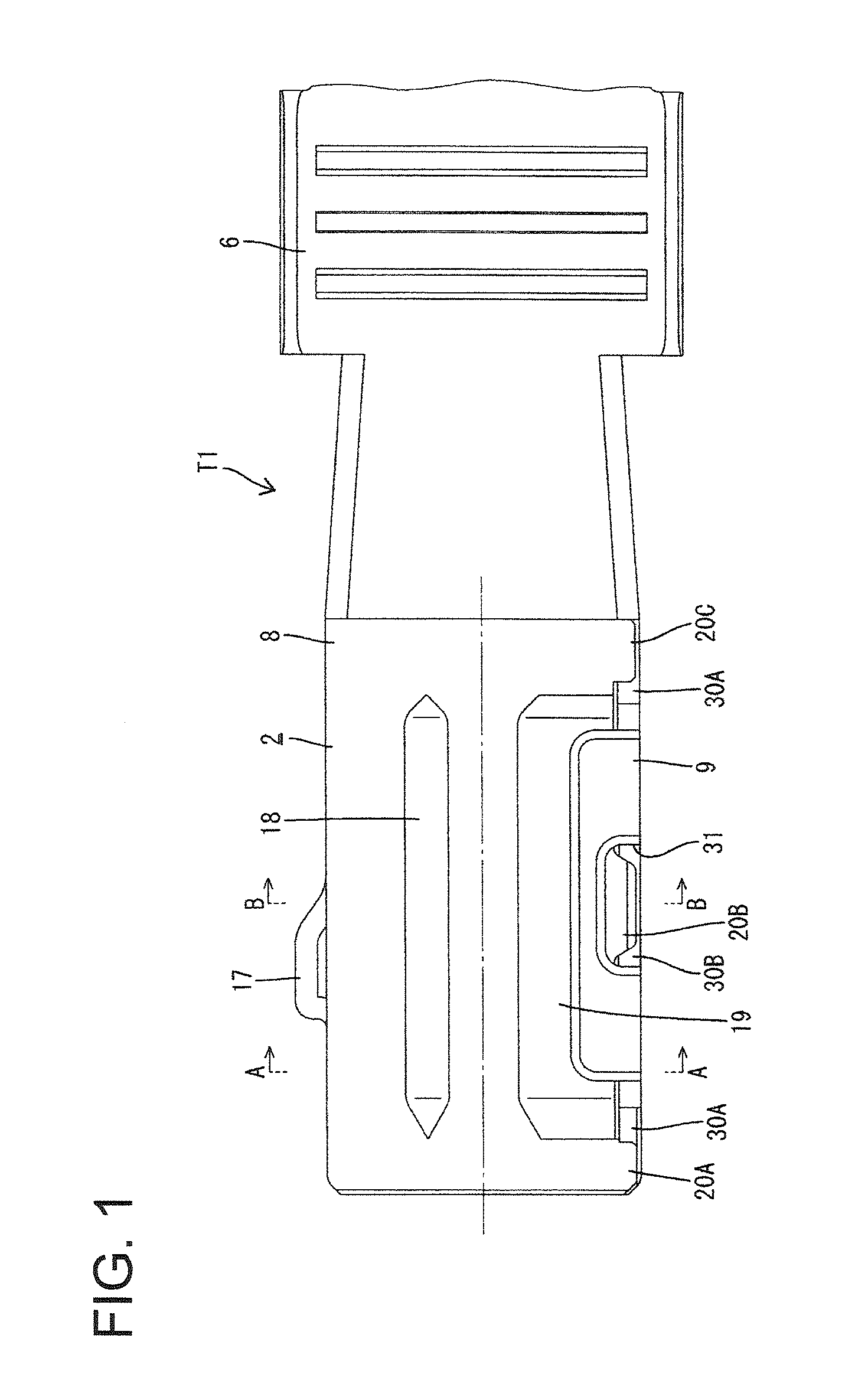
[0030]FIGS. 1 to 6 show a first particular embodiment of the present invention. As shown in FIG. 5, a terminal fitting T1 is in a developed state after a conductive plate material is punched or cut out into a specified shape. A multitude of terminal fittings T1 in the developed state are coupled to a carrier 1 in a chain-like manner in a longitudinal direction of the carrier 1. The terminal fittings T1 in the developed state are cut off from the carrier 1 in a later step and assembled as the terminal fittings T1 having a desired shape after respective bending, folding, embossing, punching, stamping and / or striking steps.

[0031]A hollow (in forward and backward directions) rectangular or polygonal tube 2 is formed on or near the front of each terminal fitting T1 and a wire connection portion comprising at least one wire barrel 6 to be crimped and connected to a wire core and at least one insulation barrel 7 to be crimped and connected to a wire coating to be connected to a wire is fo...

fourth embodiment

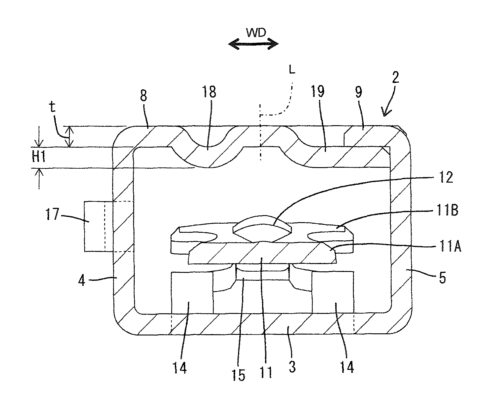
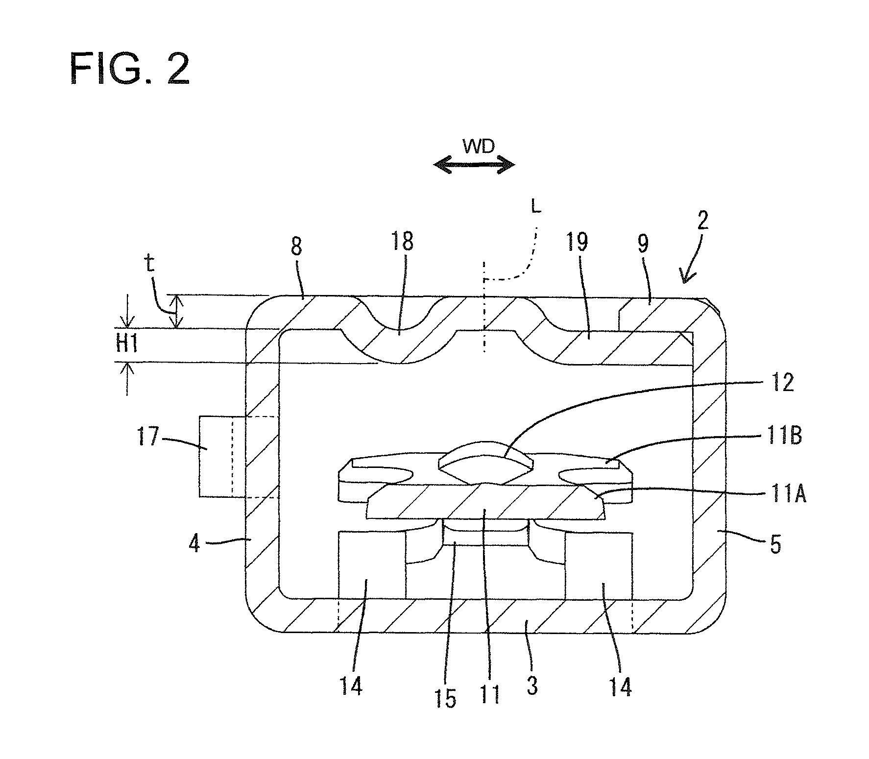
[0052]However, in the fourth embodiment, a ceiling plate 8 is deformed (e.g. struck or embossed or bent) such that a ceiling plate side contact portion 18 and a struck or bent portion 19 are continuous without forming any boundary. Specifically, the ceiling plate 8 is struck to have a substantially uniform depth over a width range extending from a position near a first side plate 4 to the extending end edge thereof, and the inner surface of this struck or bent part can be held in surface contact with a mating terminal M over a specified width range. The depth of this struck or bent part corresponds to a plate thickness as in the other embodiments.

[0053]Other configurations are similar or same as in the other embodiments and, hence, similar functions and effects can be achieved.

[0054]The invention is not limited to the above described and illustrated embodiments. For example, the following embodiments are also included in the technical scope of the present invention.

[0055]The height ...


PUM


Abstract

A terminal fitting has a rectangular tube (2) with a ceiling plate (8). A struck portion (19) is formed by striking an extending end edge of the ceiling plate (8) inwardly of the rectangular tube (2) while maintaining a plate thickness. The inner surface of this struck portion (19) is at the same height as the projecting end of a ceiling plate side contact portion (18) and the outer surface of the struck portion (19) is at the same height as the inner surface of the ceiling plate (8) around the contact portion. A pressing portion (9) is bent from the upper end edge of a second side plate (5) to extend substantially parallel to a bottom plate (3) and contacts the outer surface of the struck portion (19). The pressing portion (9) does not project in a height direction from the ceiling plate (8).

Description

BACKGROUND[0001]1. Field of the Invention[0002]The invention relates to a terminal fitting and a method of producing it.[0003]2. Description of the Related Art[0004]Generally, a female terminal fitting includes a rectangular tube into which a male tab is inserted. The rectangular tube is formed by a pair of side plates that stand at right angles from opposite left and right side edges of a bottom plate. A ceiling plate extends from the upper edge of one side plate to the upper edge of the other side plate. A pressing portion extends from the upper end edge of one side plate to the bottom plate and is placed on the ceiling plate to prevent it from opening. When the pressing portion is placed over the ceiling plate, the rectangular tube is often too bulky.[0005]U.S. Pat. No. 7,347,747 discloses recessing an area of the ceiling plate where the pressing portion is to be placed by pressing to make the terminal fitting less bulky. However, pressing the ceiling plate creates other problems...

Claims


Application Information

Patent Timeline
Patent Type & Authority Patents(United States)
IPC IPC(8): H01R11/22H01R13/11
CPCH01R13/11H01R13/113
Inventor AMANO, TAKAMARUTANAKA, TSUTOMU
Owner SUMITOMO WIRING SYST LTD
Why Eureka
Try Eureka