Permanent slipping rotating band and method for producing such a band

a technology of rotating bands and projectiles, which is applied in the direction of ammunition projectiles, weapons components, ammunition, etc., can solve the problems that permanent and fixedly mounted rotating bands cannot be used for roll-stable guidable projectiles, and increase the risk of persons and equipment in the surrounds of launchers, so as to reduce the risk of unwanted injuries or damage, the effect of increasing the risk of peopl

Active Publication Date: 2015-02-10
BAE SYST BOFORS
View PDF22 Cites 5 Cited by
  • Summary
  • Abstract
  • Description
  • Claims
  • Application Information

AI Technical Summary

Benefits of technology

[0024]In the currently existing solutions for slipping rotating bands, a rotating band made of plastics material is used, which plastics rotating band detaches from the projectile, wholly or in parts, following launch from the barrel. Once the rotating band has been accelerated to the same speed as the projectile, then the rotating band or parts of the rotating band will, per se, become one or more projectiles and give rise to an increased risk for persons and equipment in the vicinity of the launcher. By eliminating the prospect of the rotating band leaving the projectile, the risk of unwanted injuries or damage is reduced.LIST OF FIGURES
[0025]The invention will be described in greater detail below with reference to the appended figures, in which:
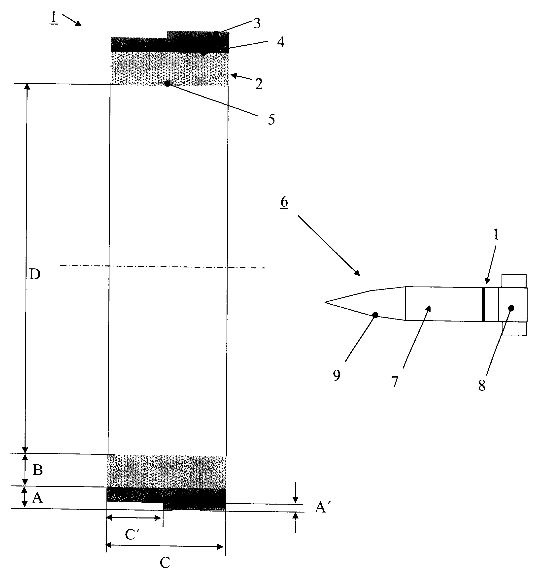
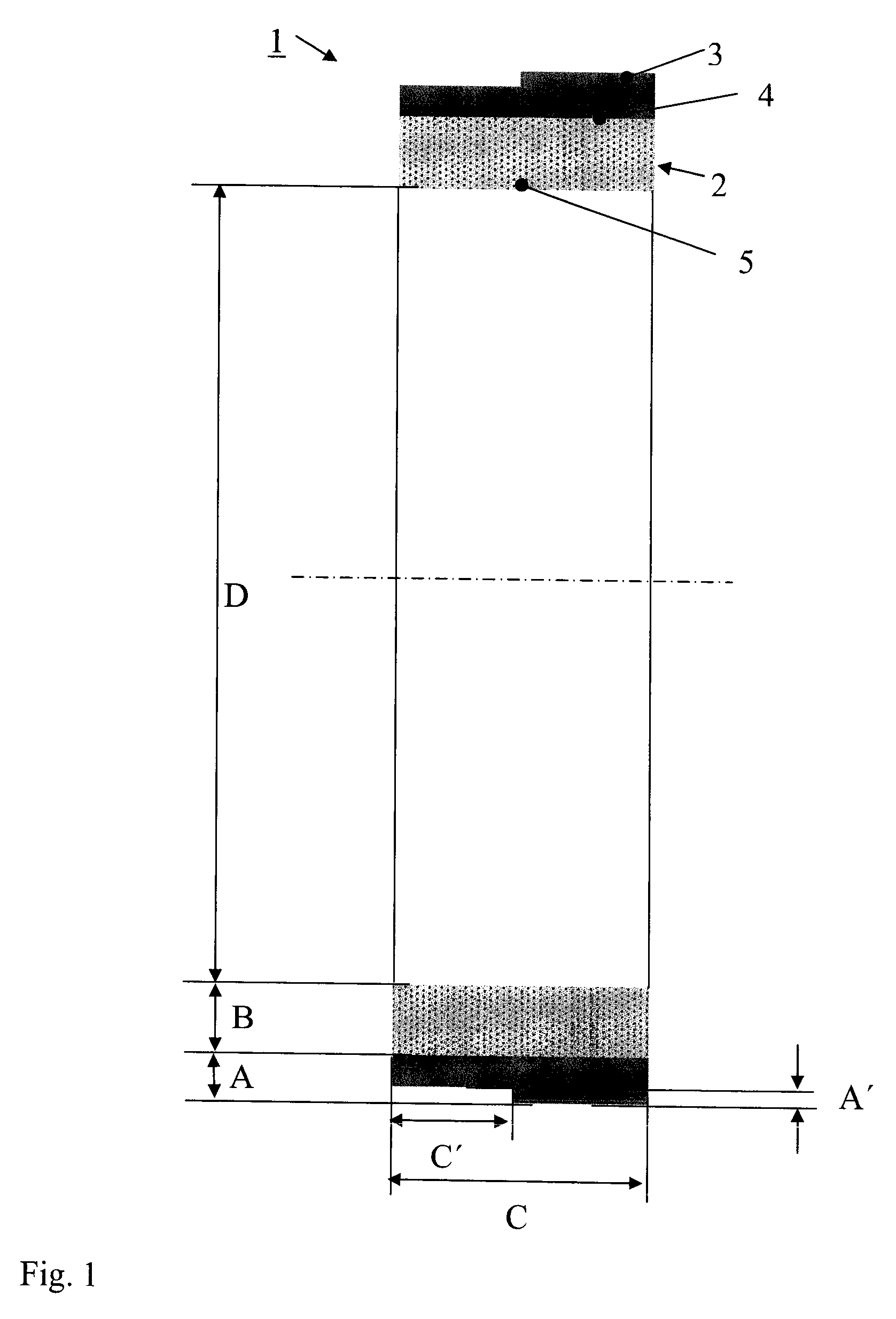
[0026]FIG. 1 shows a rotating band in cross section according to the invention,
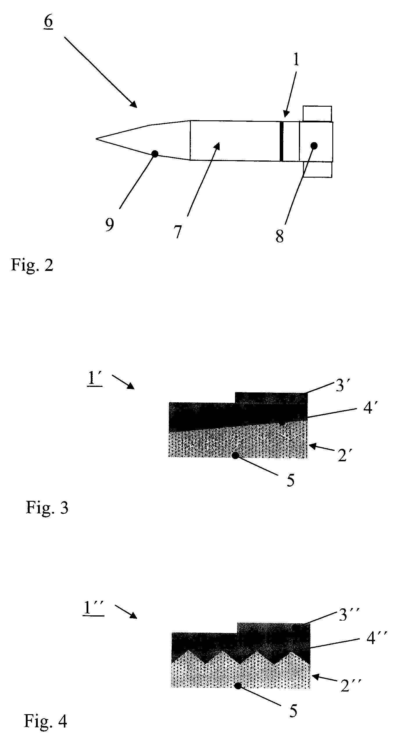
[0027]FIG. 2 shows a projectile for artillery according to the invention, with rotating band according to the invention,
[0028]FIG. 3 shows an alternative embodiment of the rotating band according to the invention,
[0029]FIG. 4 shows another alternative embodiment of the rotating band according to the invention.DETAILED

Problems solved by technology

Once the rotating band has been accelerated to the same speed as the projectile, then the rotating band or parts of the rotating band will, per se, become one or more projectiles and give rise to an increased risk for persons and equipment in the surrounds of the launcher.
Permanent and fixedly mounted rotating bands cannot therefore be used for roll-stable guidable projectiles.

Method used


Image

  • Permanent slipping rotating band and method for producing such a band
  • Permanent slipping rotating band and method for producing such a band
  • Permanent slipping rotating band and method for producing such a band

Examples


Embodiment Construction

[0030]In FIG. 1 is shown that embodiment of the rotating band 1 which consists of an inner ring 2, with thickness B, and an outer ring 3, with thickness A, in which the inner ring 2 is made of a load-bearing and dimensionally strong material which is dimensionally stable along the path of the projectile. The material in the inner ring 2 is chosen to give low friction when the ring 2 rotates against the projectile body, even though it is conceivable that the surface 5 between the inner ring 2 and the projectile body can be surface-treated to create low friction or otherwise reduce the friction. In order to achieve sufficiently good load-bearing capacity both during launch and along the path of the projectile from launcher to target, the inner ring 2 must be reinforced with fibres or particles, for example carbon fibres, aramid fibres or glass fibre. The surface 5 between the inner ring 2 and the projectile body is configured such that rotation of the rotating band relative to the pro...


PUM


Abstract

The invention relates to a projectile (6) provided with a slipping rotating band (1) which is designed for firing from a weapon system with a rifled barrel. The rotating band (1) comprises an inner ring (2) and an outer ring (3) that seals against the barrel. The outer ring is fitted on the outer surface of the inner ring and the inner ring is slippably fitted on the projectile. The rotating band (1) is configured to remain fitted on the projectile (6) from launcher to target by virtue of the fact that the inner ring (2) is made of fibre-reinforced polymer composite or particle-reinforced polymer composite, or fibre-reinforced metal matrix composite or particle-reinforced metal matrix composite. The invention also relates to a slipping rotating band (1) and to a method for producing a slipping rotating band (1) in which the outer ring (3) is affixed to the inner ring (2).

Description

CROSS REFERENCE TO RELATED APPLICATIONS[0001]This application is a National Phase filing under 35 U.S.C. §371 of PCT / SE2012 / 000052 filed on Apr. 12, 2012; and this application claims priority to Application No. 1130028-2 filed in Sweden on Apr. 14, 2011, under 35 U.S.C. §119; the entire contents of all are hereby incorporated by reference.TECHNICAL FIELD[0002]The present invention relates to a projectile provided with a slipping rotating band designed for firing from a weapon system with rifled barrel. The rotating band comprises an inner concentric ring and an outer concentric ring that seals against the barrel. The outer ring is fitted on the outer surface of the inner ring and the said inner ring is slippably fitted on the projectile. The invention further relates to a slipping rotating band intended to be slippably fitted on a projectile, which rotating band comprises an inner and an outer concentric ring. In addition thereto, the invention further relates to a method for produc...

Claims


Application Information

Patent Timeline
Patent Type & Authority Patents(United States)
IPC IPC(8): F42B14/02
CPCF42B14/02
Inventor STROMBERG, SVENCARLQVIST, LARS-.ANG.KELIDGREN, JOHANNILSSON, ANDREASSVANBERG, LARS-PETER
Owner BAE SYST BOFORS
Why Eureka
Try Eureka