
Pneumatic tire

a pneumatic tire and tread technology, applied in the field of pneumatic tires, can solve the problems of deterioration of tire durability and damage to the tread surface, and achieve the effects of reducing the stiffness of the tread, preventing stone retention in the small hole, and suppressing road nois

Active Publication Date: 2015-02-10
THE YOKOHAMA RUBBER CO LTD
View PDF22 Cites 4 Cited by
  • Summary
  • Abstract
  • Description
  • Claims
  • Application Information

AI Technical Summary

Benefits of technology

[0005]To solve the above-described problem, an object of the present invention is to provide a pneumatic tire which has many small holes provided to a land portion in a shoulder region of a tread surface in order to reduce road noise, and which is configured to prevent stone retention in the small holes, and thereby to improve the durability.
[0016]According to the present invention, the projection having the upper end with the flat surface or the convex surface is formed inside each of the small holes in the pneumatic tire, in which the multiple land portions are defined at a pitch variable in the circumferential direction of the tire by the multiple lug grooves which are arranged in each of both shoulder sections of the tread surface and each of which extends in the width direction of the tire, and in which the many small holes are aligned in the multiple land portions in the circumferential direction of the tire so that the road noise can be suppressed. Hence, the projection acts to push back a small stone which would otherwise enter the small hole, so that stone retention in the small hole can be prevented. In addition, the distance between the outer wall of the upper end portion of the projection and the inner wall of the small hole is set to 1 to 5 mm. Hence, the tread stiffness can be sufficiently reduced even when the projection is provided to suppress the stone retention, and the road noise is thereby suppressed. Moreover, since the upper end of the projection is positioned lower than the opening of the small hole, chipping of the projection can be prevented, so that the durability can be improved.

Problems solved by technology

However, since small stones and the like on a road surface are likely to be retained in the many small holes provided to the tread during driving, there is a problem that when the small holes are clogged with such small stones, the tread surface is damaged, and hence the durability of the tire is deteriorated.

Method used


Image

  • Pneumatic tire
  • Pneumatic tire
  • Pneumatic tire

Examples


examples

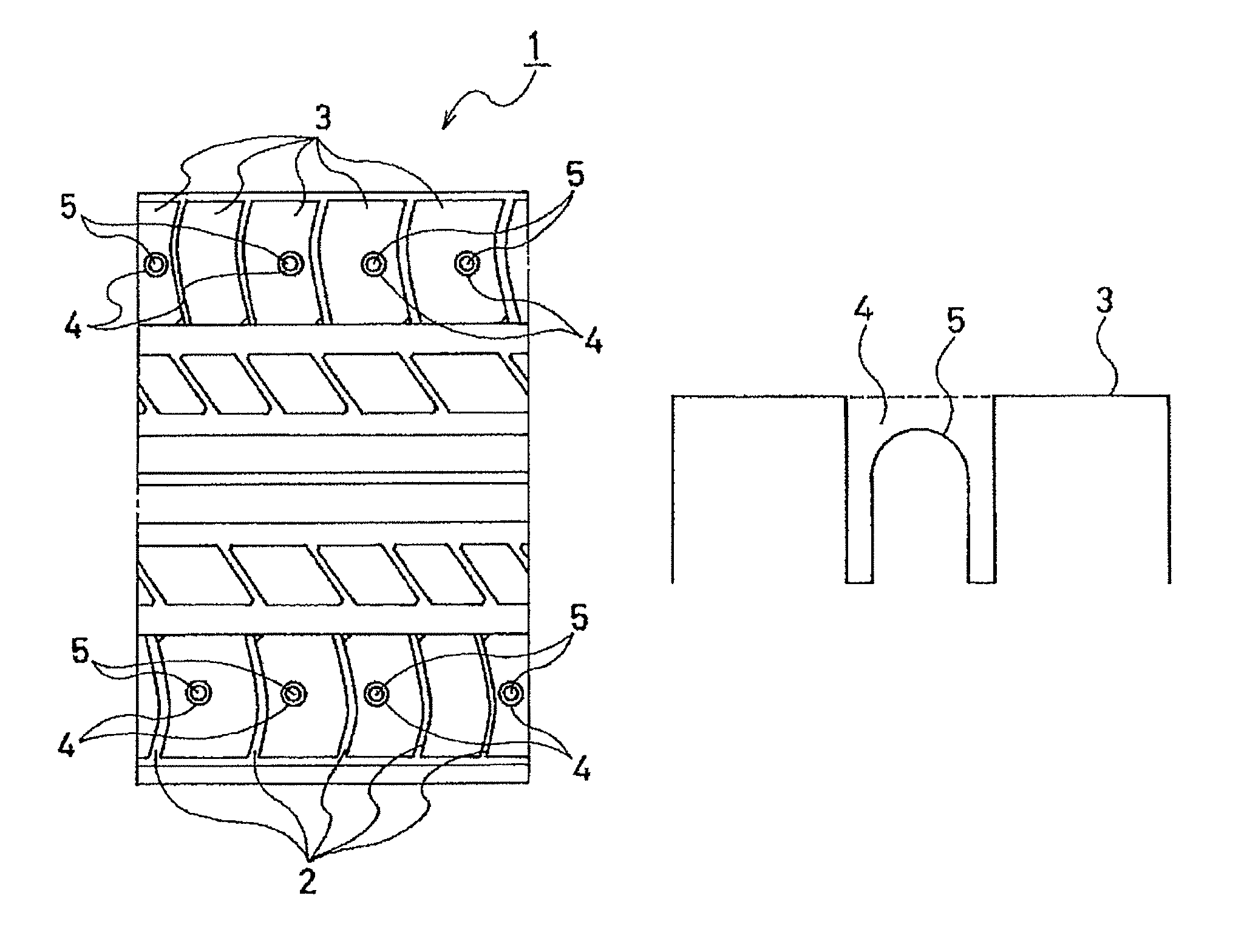
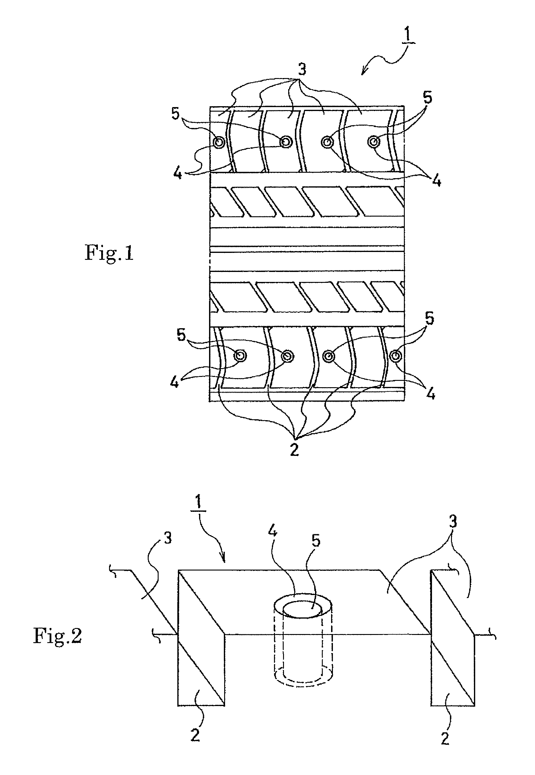
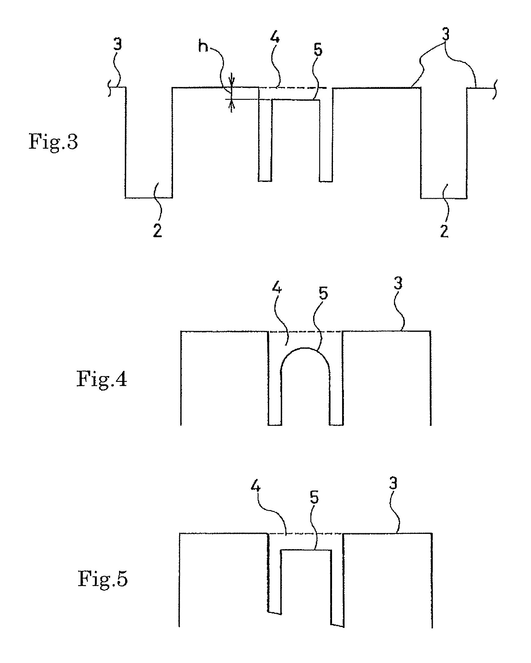
[0043]Seven kinds of pneumatic tires of Comparative Examples 1 to 3 and Examples 1 to 4 were fabricated. All seven kinds of pneumatic tires commonly had a tire size of 215 / 60R16 95H, a tread pattern of FIG. 1, and were provided with small holes having a diameter of 5 mm in shoulder sections. Specifications of the small holes and projections were different among the pneumatic tires as shown in Table 1.

[0044]Comparative Example 1 is an example where only small holes were provided, but no projections were provided. Comparative Examples 2 and 3 are examples where columnar projections were provided. Comparative Example 2 is an example where the distance between the small hole and the projection was as narrow as 0.5 mm, while Comparative Example 3 is an example where upper ends of the projections were flush with the tread surface. Each of Examples 1 to 4 is an example where projections were provided. Example 1 is an example where columnar projections were provided, the distance between th...


PUM


Abstract

A pneumatic tire is provided with a large number of holes that are arranged in the tire's circumferential direction. These holes are provided in land portions that are provided in both shoulder sections of a tread. The land portions can have different pitch lengths. Each of the holes has formed there inside a projection having an upper end with a flat surface or a convex surface. The distance between the outer wall of the projection at the upper end thereof and the inner wall of the hole is set in the range from 1 to 5 mm. The upper end of the projection is located at a position below the opening of the hole.

Description

CROSS-REFERENCE TO RELATED APPLICATIONS[0001]This U.S. National stage application claims priority under 35 U.S.C. §119(a) to Japanese Patent Application No. 2008-282106, filed in Japan on Oct. 31, 2008, the entire contents of which are hereby incorporated herein by reference.TECHNICAL FIELD[0002]The present invention relates to a pneumatic tire, and more specifically to a pneumatic tire configured to prevent stone retention in small holes provided in a land portion in a shoulder region of a tread surface for reduction of road noise.BACKGROUND ART[0003]When a rolling tire is caused to vibrate by irregularities on a road surface, the vibration is transmitted to the vehicle cabin through suspensions, and further vibrates the ceiling, floor, and the like of the vehicle cabin. A resonance sound generated by resonance of air inside the vehicle cabin due to the vibration is referred to as road noise.[0004]A conventional pneumatic tire is disclosed in Japanese patent application Kokai publi...

Claims


Application Information

Patent Timeline
Patent Type & Authority Patents(United States)
IPC IPC(8): B60C11/117B60C11/03
CPCB60C11/032B60C11/0318
Inventor TANNO, ATSUSHIFUJII, HIROSHI
Owner THE YOKOHAMA RUBBER CO LTD
Learn More