Tire with recessed portions formed on buttress portion

a buttress and recessed technology, applied in the field of tires, can solve the problems of increasing road noise and road noise, and achieve the effect of suppressing the generation of road noise due to the vibration of the buttress portion and reducing road nois

Inactive Publication Date: 2014-07-22
BRIDGESTONE CORP
View PDF13 Cites 1 Cited by
  • Summary
  • Abstract
  • Description
  • Claims
  • Application Information

AI Technical Summary

Benefits of technology

[0007]In other words, when the road surface is smooth, the buttress portion does not contact the road surface. On the other hand, when there are small dents and bumps on the road surface, such as a paved road with a rough road surface, the buttress portion does contact the road surface, and due to these dents and bumps, the buttress portion vibrates. Vibration of the buttress portion like this increases road noise.
[0008]Therefore, an object of the present invention is to provide a tire which further reduces road noise by suppressing the generation of road noise due to the vibration of the buttress portion.
[0011]According to such feature, a recessed shoulder region having a predetermined width extends along the tire circumference direction TC, and on the recessed shoulder region, a plurality of recessed portions and a surface portion are formed. By this, even in cases where there are small dents and bumps on the road surface, the dents and bumps of the road surface do not contact the recessed portions, and the area of the recessed shoulder region which contacts the road surface is reduced. For this reason, the increase of the contact pressure of the tread is suppressed, and the vibration of the recessed shoulder region due to the dents and bumps of the road surface is suppressed. Accordingly, the generation of road noise due to the vibration of the recessed shoulder region can be suppressed, and as a result, a tire further reducing road noise can be provided.
[0012]Especially, compared to cases where the recessed portions take up less than 60% of the recessed shoulder region, suppression of the reduction in shearing rigidity of the recessed shoulder region and reduction of the area of the recessed shoulder region which contacts the road surface can both be managed. Due to this, while suppressing the generation of road noise, qualities such as controlling stability and cornering performance can be maintained.
[0027]According to the features of the present invention, the generation of road noise due to the vibration of the buttress portion can be suppressed, and a tire further reducing road noise can be provided.

Problems solved by technology

Incidentally, nowadays, as a result of progress in the intensive study on the mechanism of road noise generated, it has been made clear that due to dents and bumps of the road surface, the vibration of the buttress portion is also a cause of road noise.
Vibration of the buttress portion like this increases road noise.

Method used


Image

  • Tire with recessed portions formed on buttress portion
  • Tire with recessed portions formed on buttress portion
  • Tire with recessed portions formed on buttress portion

Examples


first embodiment

[First Embodiment]

[0041]In the following, a pneumatic tire 1 according to a first embodiment will be explained. Specifically, (1) Overall configuration of pneumatic tire, (2) Detailed configuration of recessed shoulder region, (3) Comparative evaluations, (4) Operation and effect, and (5) Modifications will be explained.

(1) Overall Configuration of Pneumatic Tire

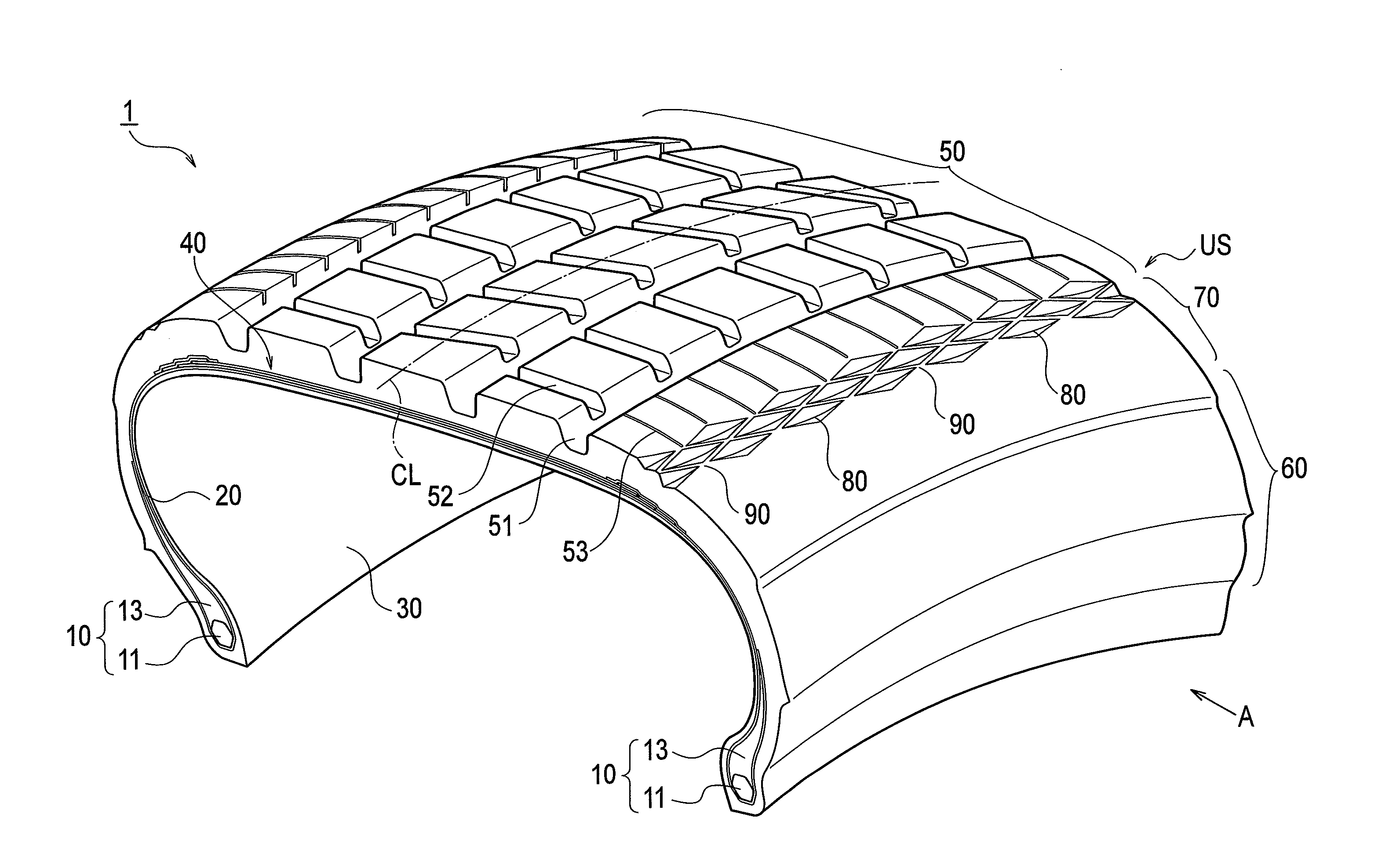
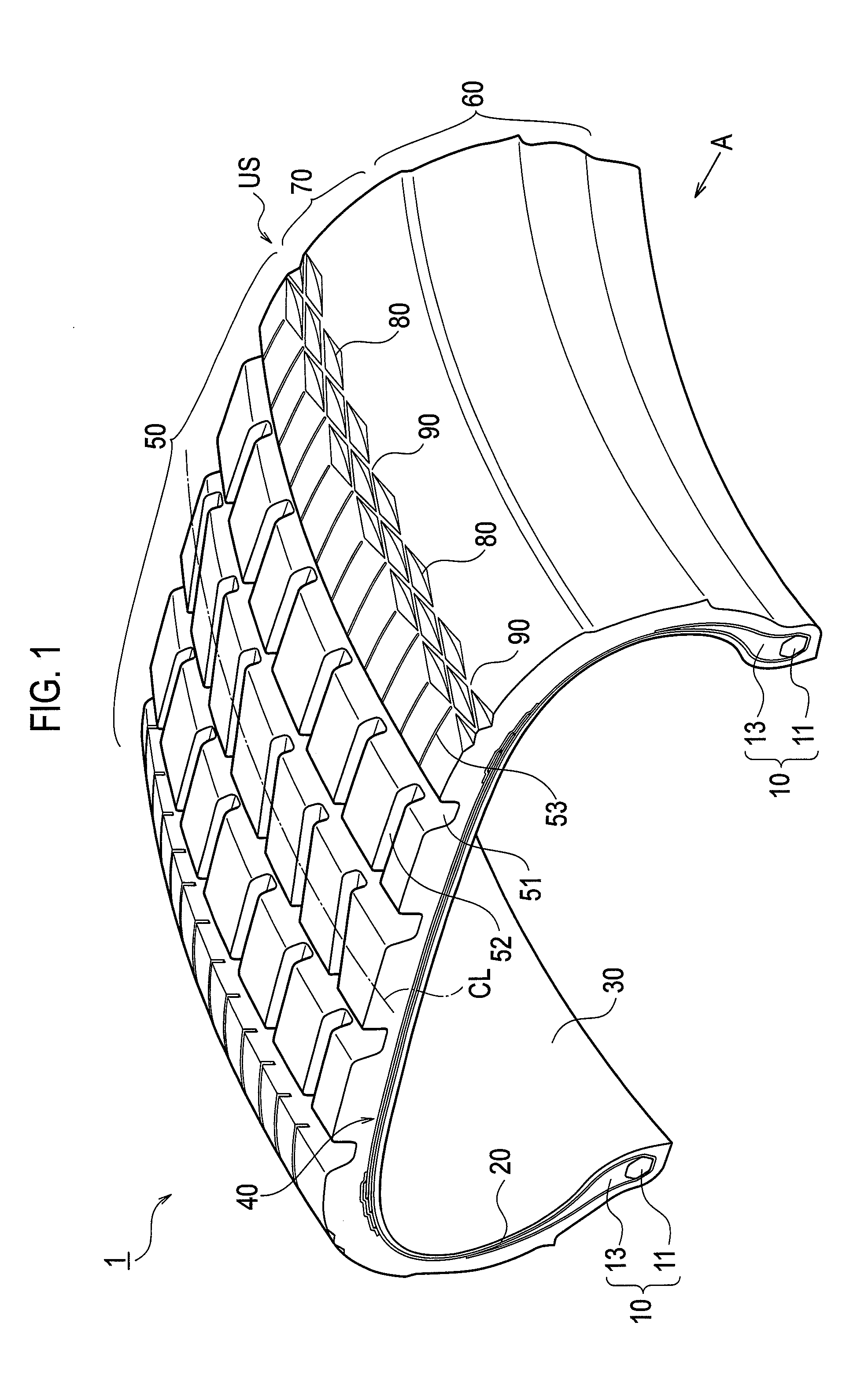
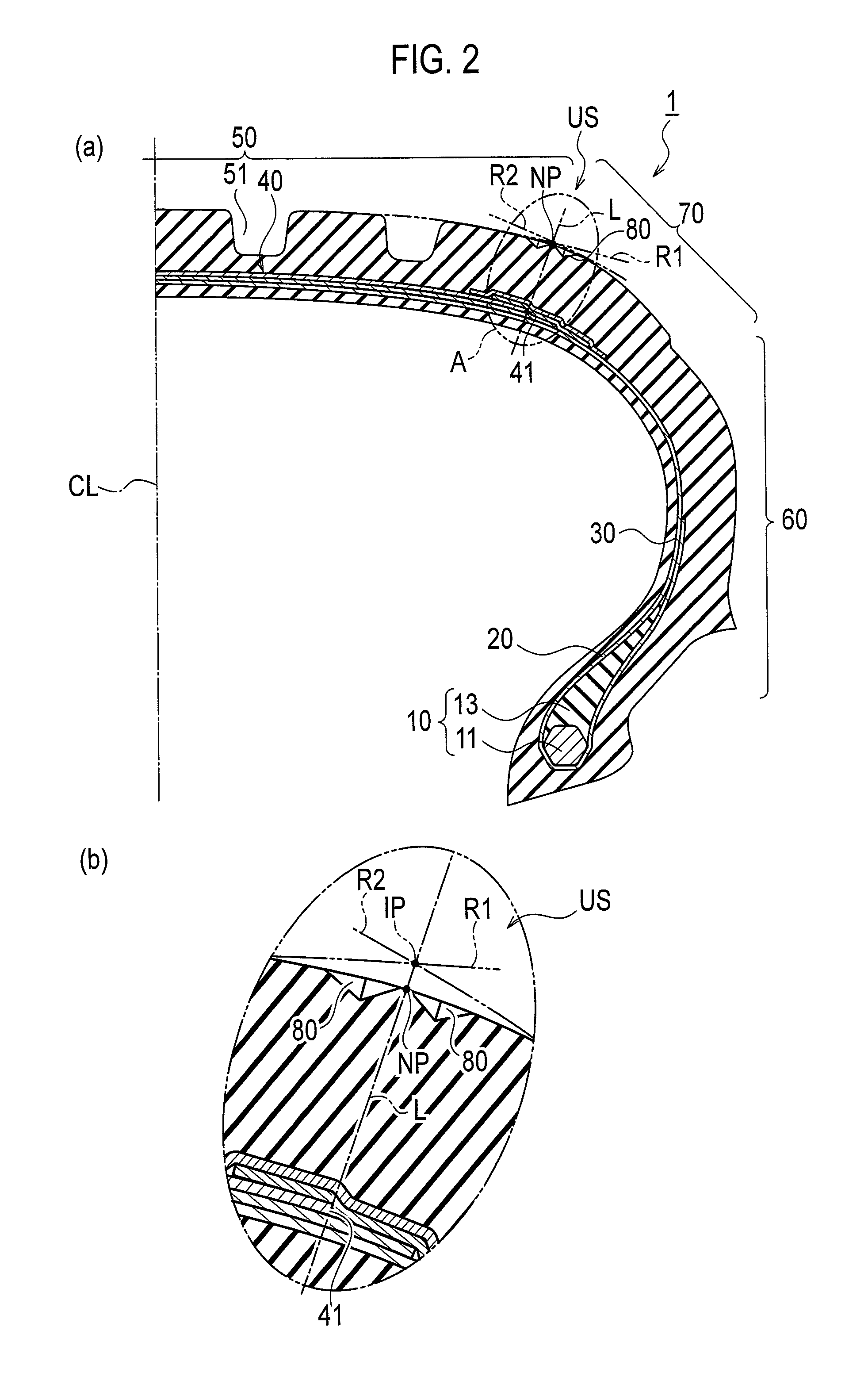
[0042]First, the overall configuration of the pneumatic tire 1 according to the first embodiment will be explained while referring to the drawings. FIG. 1 is a perspective view illustrating a part of the pneumatic tire 1 according to the first embodiment. FIG. 2(a) is a cross-sectional view in the tread width direction of the pneumatic tire 1 according to the first embodiment. FIG. 2(b) is an enlarged view illustrating an area enclosed by the double dot and dash line A of FIG. 2(a). Furthermore, the pneumatic tire 1 may be filled with, other than air, an inert gas such as nitrogen gas.

[0043]As illustrated in FIG. 1 and FIG. ...

first modification

(5-1) First Modification

[0095]First, the configuration of a recessed portion 180 of the pneumatic tire 1 according to a first modification will be explained while referring to the drawings. FIG. 6 is a tread developed view illustrating the area around the recessed shoulder region US according to the first modification.

[0096]In the first embodiment described above, the recessed portion 80 is rhombic, and the sides 81 that form the recessed portion 80 are slanted in relation to the tire circumference direction TC. In contrast, in the first modification, as illustrated in FIG. 6(a), the recessed portion 180 is rectangular. Also, the sides 181 that form the recessed portion 180 are provided along the tire circumference direction TC or the tire radial direction TR.

[0097]Also, the recessed portion 180 is not necessarily required to be rectangular, and as illustrated in FIG. 6(b), may be triangular, and the shape of the recessed portion 180 may be appropriately varied to correspond to diff...

second modification

(5-2) Second Modification

[0098]Next, the configuration of a recessed portion 280 of the pneumatic tire 1 according to a second modification will be explained while referring to the drawings. FIG. 7 is a tread developed view illustrating the area around the recessed shoulder region US according to the second modification.

[0099]In the first embodiment described above, the recessed portion 80B is provided in a position shifted, in the tire circumference direction TC, from that of the recessed portion 80A and the recessed portion 80C. In contrast, in the second modification, as illustrated in FIG. 7(a) and FIG. 7(b), a recessed portion 280A, a recessed portion 280B, and a recessed portion 280C are provided in such a way that they are lined up in the tire circumference direction TC. Furthermore, with the recessed portions 280 illustrated in FIG. 7(b), the surface portion 90 does not necessarily have to be formed surrounding each of the recessed portions 280, and may be provided as a pred...


PUM


Abstract

A pneumatic tire (1) comprises a tread (50), side walls (60), and buttress portions (70). In a cross-section of the pneumatic tire (1) in the tread width direction (TW), if the point at which a first curved line (R1) which follows the curvature of the surface of the tread (50) and a second curved line (R2) which follows the curvature of the surface of a buttress portion (70) intersect is defined as an imaginary point (IP) and also if the point at which a straight line (L) passing through the imaginary point (IP) and substantially perpendicular to the carcass (20) intersects the surface of the pneumatic tire (1) is defined as an intersection point (NP), the pneumatic tire (1) has a recessed shoulder region (US) including the intersection point (NP) and having a predetermined width. The recessed shoulder region (US) is provided with recesses (80) recessed from the surface of the pneumatic tire (1) and also with a surface portion (90) in which no recess (80) is formed. The recessed shoulder region (US) extends in the tire circumference direction (TC).

Description

CROSS REFERENCE TO RELATED APPLICATIONS[0001]This application is a National Stage of International Application No. PCT / JP2010 / 051107 filed Jan. 28, 2010, claiming priority based on Japanese Patent Application Nos. 2009-200815, filed Aug. 31, 2009 and 2010-006954, filed Jan. 15, 2010, the contents of all of which are incorporated herein by reference in their entirety.TECHNICAL FIELD[0002]The present invention relates to a tire having a tread which contacts the road surface, side walls provided on the inner side, in the tire radial direction, of the tread, and a buttress portion provided between the tread and the side walls.BACKGROUND ART[0003]Conventionally, in tires mounted on vehicles such as a passenger vehicle, various methods have been used to reduce road noise generated when the tire rolls on a road surface having irregular dents and bumps, such as a paved road with a rough road surface. For example, there is known a tire using rubber with high stiffness in the shoulder portion...

Claims


Application Information

Patent Timeline
Patent Type & Authority Patents(United States)
IPC IPC(8): B60C11/01B60C13/02
CPCB60C11/01B60C13/001B60C2011/1361B60C5/00B60C11/04B60C11/13
Inventor KOJIMA, TAKAAKIKIWAKI, YUKIHIRO
Owner BRIDGESTONE CORP
Why Eureka
Try Eureka