Flash light device

a flash light and flash light technology, applied in the field of flash light devices, can solve the problems of inability to effectively reduce the over-exposure of an object with high reflectivity, unstable flash light flash intensity, and likely over-exposure of captured images, so as to reduce the problem of over-exposure

Inactive Publication Date: 2015-02-10
ALTEK CORP
View PDF12 Cites 3 Cited by
  • Summary
  • Abstract
  • Description
  • Claims
  • Application Information

AI Technical Summary

Benefits of technology

[0009]Accordingly, the invention is directed to a flash light device able to reduce the over-exposure problem.
[0019]Based on the description above, the invention provides a driving voltage required for driving the light diffuser according to a voltage information so as to adjust the light energy of the flash light after penetrating the light diffuser and reduce the over-exposure problem. The voltage information herein is determined according to an original image without light-complementing of the light source and a pre-flash image with light-complementing of the light source.

Problems solved by technology

Since a flash light has a light intensity much higher than the environment's light intensity, so that when a flash light directly irradiates onto an object, if the flash light is too close to the object or the material of the object has easily-reflecting characteristic, the captured image is likely over-exposed.
Although in step S104, for estimating the flashing intensity of the flash light required during shooting, a pre-flash method is used, but the flashing intensity of the flash light is not stable.
In this way, although the energy output of the flash light can be controlled to solve the over-exposing problem due to the distance between the object and the lens, however, it is unable to effectively reduce the over-exposing for an object with high reflectivity.

Method used


Image

  • Flash light device
  • Flash light device
  • Flash light device

Examples


Embodiment Construction

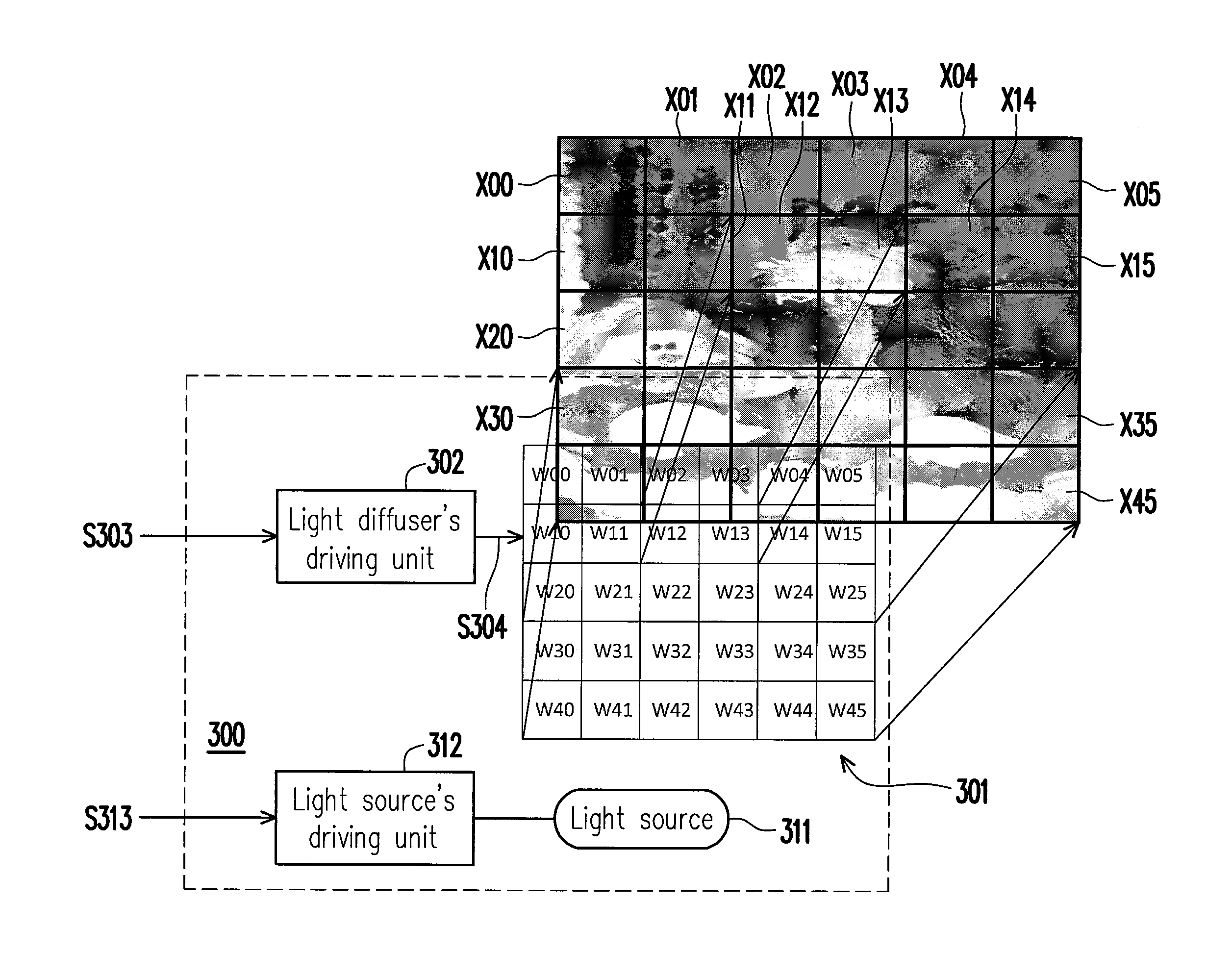
[0032]FIG. 3 is a schematic diagram of a flash light device according to an embodiment of the invention. Referring to FIG. 3, a flash light device 300 includes a light diffuser 301, a light diffuser's driving unit 302, a light source 311 and a light source's driving unit 312. The light diffuser's driving unit 302 is coupled to the light diffuser 301 and receives a set of voltage information S303. The set of voltage information S303 indicates a plurality of driving voltages S304 required by the light diffuser 301. The light diffuser's driving unit 302 produces the driving voltages S304 and apply the driving voltages S304 with a certain control timing to the light diffuser 301. The light source's driving unit 312 is coupled to the light source 311 and receives a trigger signal S313 so as to adjust the time for the light source 311 to produce flashing or the flash intensity.

[0033]The light diffuser 301 herein includes a plurality of sub-blocks (as shown by FIG. 3, W00-W45). Each of the...


PUM

PropertyMeasurementUnit
light energyaaaaaaaaaa
light penetration energyaaaaaaaaaa
driving voltageaaaaaaaaaa

Abstract

The invention provides a flash light device, which includes a light source, a light diffuser and a light diffuser's driving unit. The light diffuser's driving unit provides the light diffuser with a required driving voltage according to a voltage information, in which the voltage information is determined according to an original image without light-complementing of the light source and a pre-flash image with light-complementing of the light source.

Description

CROSS-REFERENCE TO RELATED APPLICATION[0001]This application claims the priority benefit of Taiwan application serial no. 101114216, filed on Apr. 20, 2012. The entirety of the above-mentioned patent application is hereby incorporated by reference herein and made a part of this specification.BACKGROUND OF THE INVENTION[0002]1. Field of the Invention[0003]The invention generally relates to a flash light device, and more particularly, to a flash light device able to reduce the over-exposure problem.[0004]2. Description of Related Art[0005]In general speaking, both the digital camera and the film-based camera usually respectively have an embedded flash light to facilitate the user conducting light-complementing on the object to be shot in a dim light environment or a backlight environment. Since a flash light has a light intensity much higher than the environment's light intensity, so that when a flash light directly irradiates onto an object, if the flash light is too close to the obj...

Claims


Application Information

Patent Timeline
Patent Type & Authority Patents(United States)
IPC IPC(8): H04N5/222G03B19/18G03B21/00G03B15/03G03B15/06G03B15/02A61B1/06H04N9/07
CPCG02F1/133G02F1/1334G02F2203/03G03B15/05G03B2215/0592H04N23/74
Inventor LIAW, MING-JIUN
Owner ALTEK CORP
Why Eureka
Try Eureka