Switching-device remaining lifetime diagnosis method and apparatus

a technology of switching devices and diagnostic methods, applied in the direction of electric devices, process and machine control, using mechanical means, etc., can solve the problems of deterioration of such a switching device and the expiration of the remaining lifetime of the switching device, and achieve the effect of simple configuration, simple configuration and accurate estimation of the life of the switching devi

Active Publication Date: 2015-02-17
MITSUBISHI ELECTRIC CORP
View PDF15 Cites 4 Cited by
  • Summary
  • Abstract
  • Description
  • Claims
  • Application Information

AI Technical Summary

Benefits of technology

[0018]The switching-device remaining lifetime diagnosis method of the present invention makes it possible to separate deterioration factors caused in a switching device, so that the remaining lifetime can accurately be estimated.
[0019]The switching-device remaining lifetime diagnosis method of the present invention makes it possible to estimate the remaining lifetime of a switching device even in the case of a deterioration factor that does not indicate any deterioration tendency in system data in which status amounts are arranged with the abscissa of an elapsed time, the number of operations, an inoperative time, or an accumulated time.
[0020]Even in the case where in system data in which status amounts are arranged with the abscissa of a total elapsed time during an operation period of a switching device, the number of total operations, a total inoperative time, or a total accumulated time, no deterioration tendency appears, the switching-device remaining lifetime diagnosis method of the present invention makes it possible to indicate a deterioration tendency by use of at least one of system data in which the status amounts are arranged with the abscissa of an elapsed time during a period after the time point when a predetermined period has elapsed from a time point when the switching device had initially started to operate, system data in which the status amounts are arranged with the abscissa of the number of operations of the switching device during a period after the time point when the predetermined period has elapsed, system data in which the status amounts are arranged with the abscissa of an inoperative time of the switching device during a period after the time point when the predetermined period has elapsed, and system data in which the status amounts are arranged with the abscissa of an accumulated operation time of the switching device during a period after the time point when the predetermined period has elapsed; therefore, the remaining lifetime of the switching device can more accurately be estimated with a simple configuration.
[0021]The switching-device remaining lifetime diagnosis apparatus of the present invention makes it possible with a simple configuration to separate deterioration factors caused in a switching device, so that the remaining lifetime can accurately be estimated.
[0022]The switching-device remaining lifetime diagnosis apparatus of the present invention makes it possible to more accurately estimate the remaining lifetime of a switching device.
[0023]Even in the case where in system data in which the status amounts are arranged with the abscissa of a total elapsed time during an operation period of a switching device, the number of total operations, a total inoperative time, or a total accumulated time, no deterioration tendency appears, the switching-device remaining lifetime diagnosis apparatus of the present invention makes it possible to indicate a deterioration tendency by use of at least one of system data in which the status amounts are arranged with the abscissa of an elapsed time during a period after the time point when a predetermined period has elapsed from a time point when the switching device had initially started to operate, system data in which the status amounts are arranged with the abscissa of the number of operations of the switching device during a period after the time point when the predetermined period has elapsed, system data in which the status amounts are arranged with the abscissa of an inoperative time of the switching device during a period after the time point when the predetermined period has elapsed, and system data in which the status amounts are arranged with the abscissa of an accumulated operation time of the switching device during a period after the time point when the predetermined period has elapsed; therefore, the remaining lifetime of the switching device can more accurately be estimated with a simple configuration.

Problems solved by technology

The deterioration in such a switching device develops due to contributing factors such as an elapsed time from a time point when the switching device has initially started its operation, the number of operations, the time period of non-operation, and foreign materials in its moving parts; at a certain time point, the performance characteristics thereof deviate from a predetermined service condition and the remaining lifetime thereof expires.

Method used


Image

  • Switching-device remaining lifetime diagnosis method and apparatus
  • Switching-device remaining lifetime diagnosis method and apparatus
  • Switching-device remaining lifetime diagnosis method and apparatus

Examples


embodiment 1

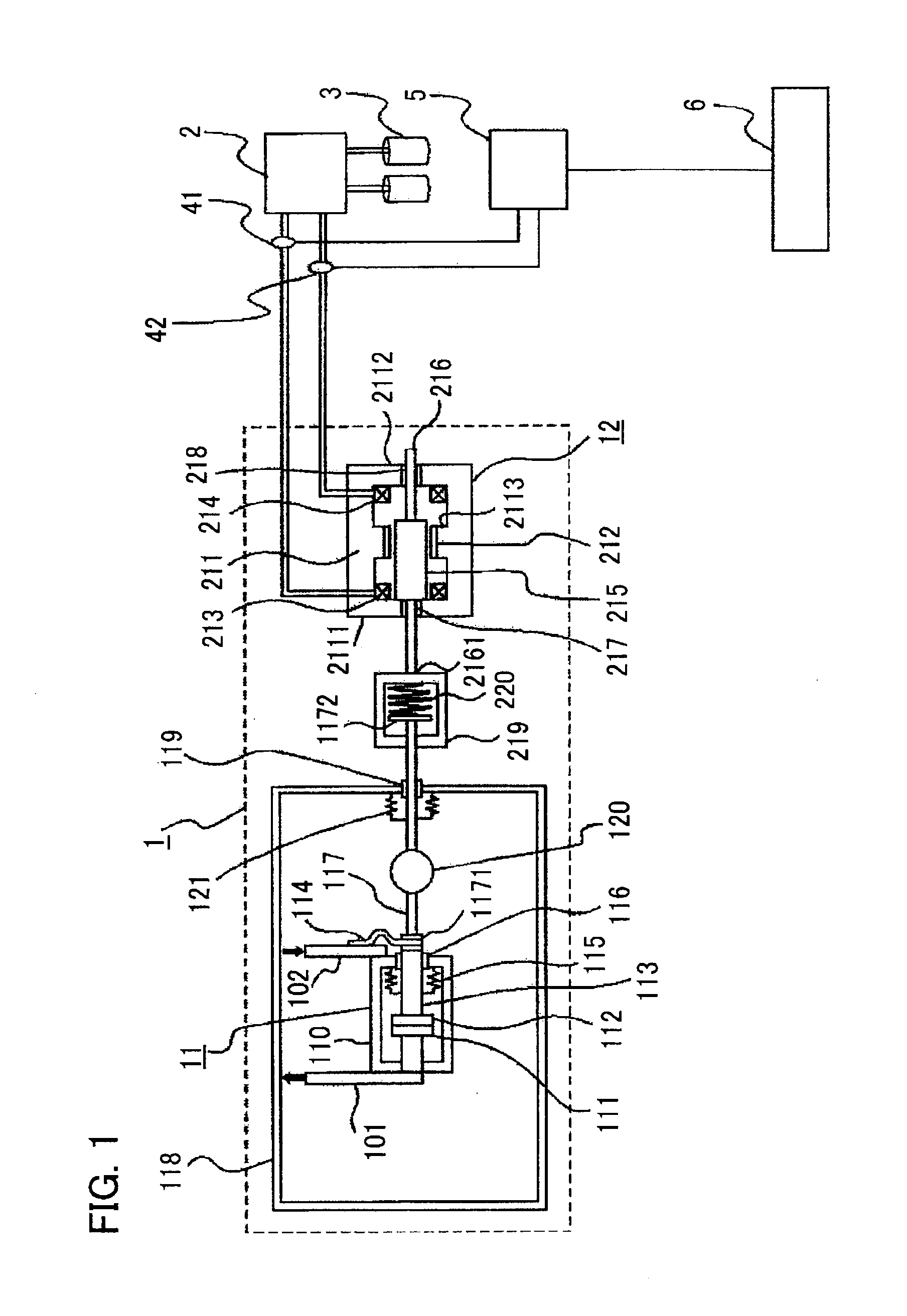
[0039]Hereinafter, a switching-device remaining lifetime diagnosis apparatus according to Embodiment 1 of the present invention will be explained in detail. FIG. 1 is a configuration diagram illustrating a switching-device remaining lifetime diagnosis apparatus according to Embodiment 1 of the present invention. A switching-device remaining lifetime diagnosis method according to Embodiment 1 of the present invention is implemented by a switching-device remaining lifetime diagnosis apparatus according to Embodiment 1, and will clearly be explained with reference to FIG. 1.

[0040]In FIG. 1, a switching device 1 is provided with a vacuum valve 11 that opens or closes a main circuit, which is an electric circuit configured with main circuit conductors 101 and 102, and an electromagnetic actuator 12, which is a driving mechanism for driving the vacuum valve 11.

[0041]The vacuum valve 11 is provided with a case 110 that is kept approximately vacuum; inside the case 110, there are contained ...

embodiment 2

[0145]FIG. 7 is a set of explanatory charts for explaining a switching-device remaining lifetime diagnosis method and a switching-device remaining lifetime diagnosis apparatus according to Embodiment 2 of the present invention; (a) is an explanatory chart for explaining a system data in which frictional forces F are arranged with the abscissa of the number of operations or the elapsed time during a period after the switching device has initially started to operate; (b) is an explanatory chart for explaining a system data in which the variance value D of the recent N-time frictional forces is arranged with the abscissa of the number of operations or the elapsed time.

[0146]In the system data represented in (a) of FIG. 7, there is recognized no correlation indicating the development of deterioration in the switching device; however, in some times, there exists a case where compared to the variation B1 in the frictional forces F in the initial operation period of the switching device, t...

embodiment 3

[0155]FIG. 8 is a set of explanatory charts for explaining a switching-device remaining lifetime diagnosis method and a switching-device remaining lifetime diagnosis apparatus according to Embodiment 3 of the present invention; (a) is an explanatory chart for explaining a system data in which frictional forces F are arranged with the abscissa of the elapsed time T during a period after the switching device has initially started to operate; (b) is an explanatory chart for explaining a system data in which frictional forces F, which are measured status amounts, are converted into status variables G by use of a transformation function fcorr, and the status variables G are arranged with the abscissa of the elapsed time.

[0156]With regard to values measured by a measurement unit such as a current sensor, status amounts such as frictional force and an operation time are stored as physical quantities. These physical quantities vary depending on the deterioration status of a switching device...


PUM


Abstract

There are provided a switching-device remaining lifetime diagnosis method and a switching-device remaining lifetime diagnosis apparatus, wherein as status amount history data, there are accumulated status amounts related to a deterioration status of a switching device, estimated based on measurement data obtained through measurement of performance characteristics of the switching device; based on the accumulated status amount history data, there are created a plurality of system data pieces in which the status amounts are arranged with the respective abscissas of an elapsed time during an operation period of the switching device, the number of operations of the switching device, an inoperative time of the switching device, and an accumulated operation time of the switching device; based on the created system data pieces, the remaining lifetime of the switching device is estimated.

Description

BACKGROUND OF THE INVENTION[0001]1. Field of the Invention[0002]The present invention relates to a switching-device remaining lifetime diagnosis method in which the remaining lifetime of a switching device is diagnosed based on the performance characteristics of the switching device and to a remaining lifetime diagnosis apparatus utilizing the remaining lifetime diagnosis method.[0003]2. Description of Related Art[0004]In general, a switching device such as an electric power switching device (simply referred to as a switching device, hereinafter) is provided with a fixed contact, a movable contact that is provided in such a way as to face the fixed contact, and a driving mechanism that drives the movable contact in such a way that the movable contact comes in contact with the fixed contact or is separated from the fixed contact. The deterioration in such a switching device develops due to contributing factors such as an elapsed time from a time point when the switching device has in...

Claims


Application Information

Patent Timeline
Patent Type & Authority Patents(United States)
IPC IPC(8): G01B7/16G01R19/165G01R11/23G01R11/25G01M99/00G01R31/327G05B23/02H01H3/00H01H33/666H01H71/04
CPCG05B23/0283G01R31/3274H01H3/001H01H33/6662H01H2071/044G01M99/00G05B23/02H02B13/00
Inventor MARUYAMA, AKIHIKOHORINOUCHI, KATSUHIKO
Owner MITSUBISHI ELECTRIC CORP
Why Eureka
Try Eureka