Check patentability & draft patents in minutes with Patsnap Eureka AI!

Device to lower NOx in a gas turbine engine combustion system

a technology of combustion system and gas turbine engine, which is applied in the direction of machines/engines, mechanical equipment, lighting and heating apparatus, etc., can solve the problems of increasing the cost and maintenance of gas turbine engines, reducing the amount of oxygen available for combustion, and producing unacceptable levels of nox emissions

Inactive Publication Date: 2015-02-24
SIEMENS ENERGY INC
View PDF21 Cites 5 Cited by
  • Summary
  • Abstract
  • Description
  • Claims
  • Application Information

AI Technical Summary

Problems solved by technology

High efficiency gas turbine engine combustors operate at high temperatures that may produce an unacceptable level of NOx emissions.
The presence of the recirculated vitiated gases reduces the amount of oxygen available for combustion.
This equipment may add to the cost and maintenance of a gas turbine engine.
Furthermore, when such equipment is connected through a casing of the gas turbine engine, the cost of the casing and the potential for leakage increase.
However, the jets increase the pressure drop across the burner which limits their application.

Method used


Image

  • Device to lower NOx in a gas turbine engine combustion system
  • Device to lower NOx in a gas turbine engine combustion system
  • Device to lower NOx in a gas turbine engine combustion system

Examples


Embodiment Construction

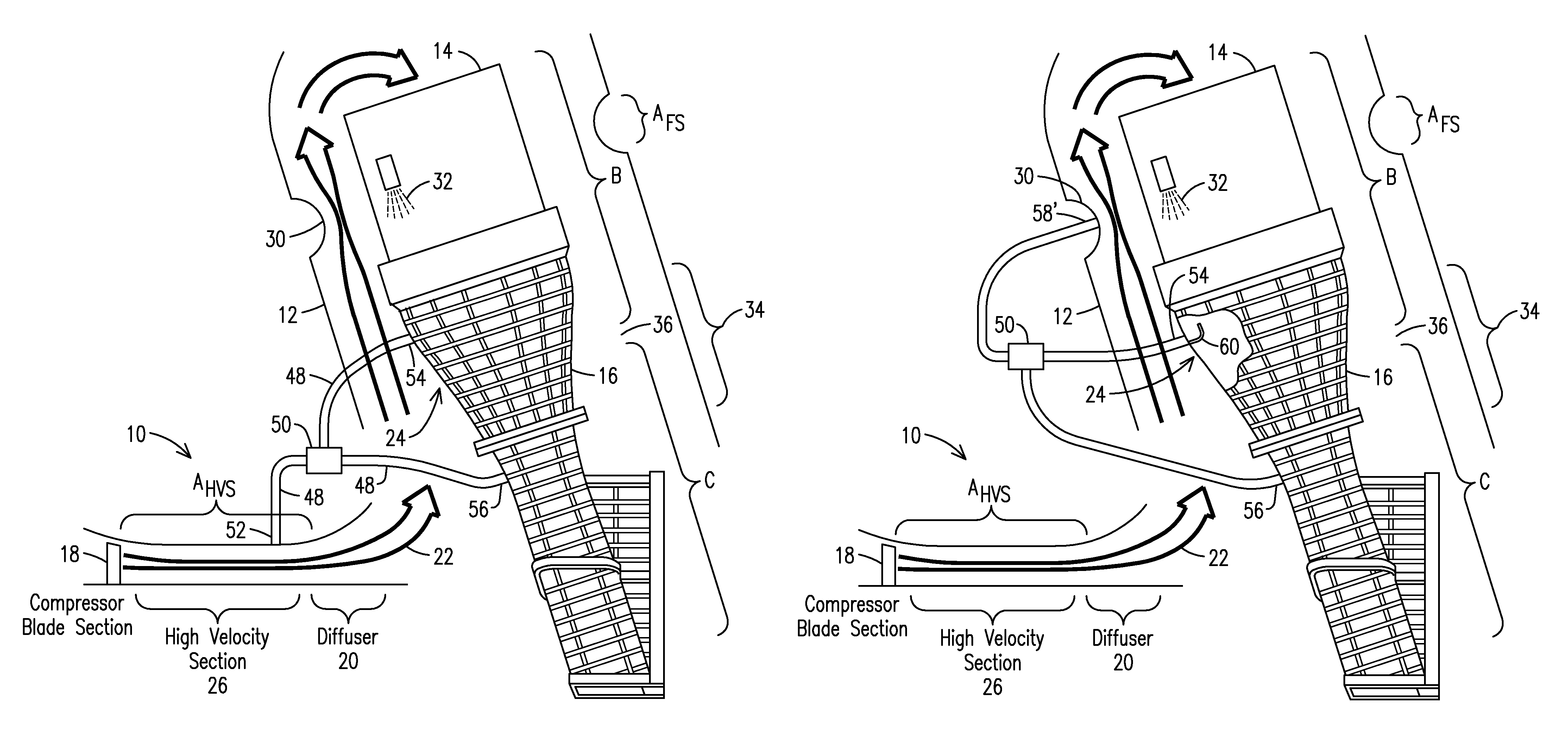
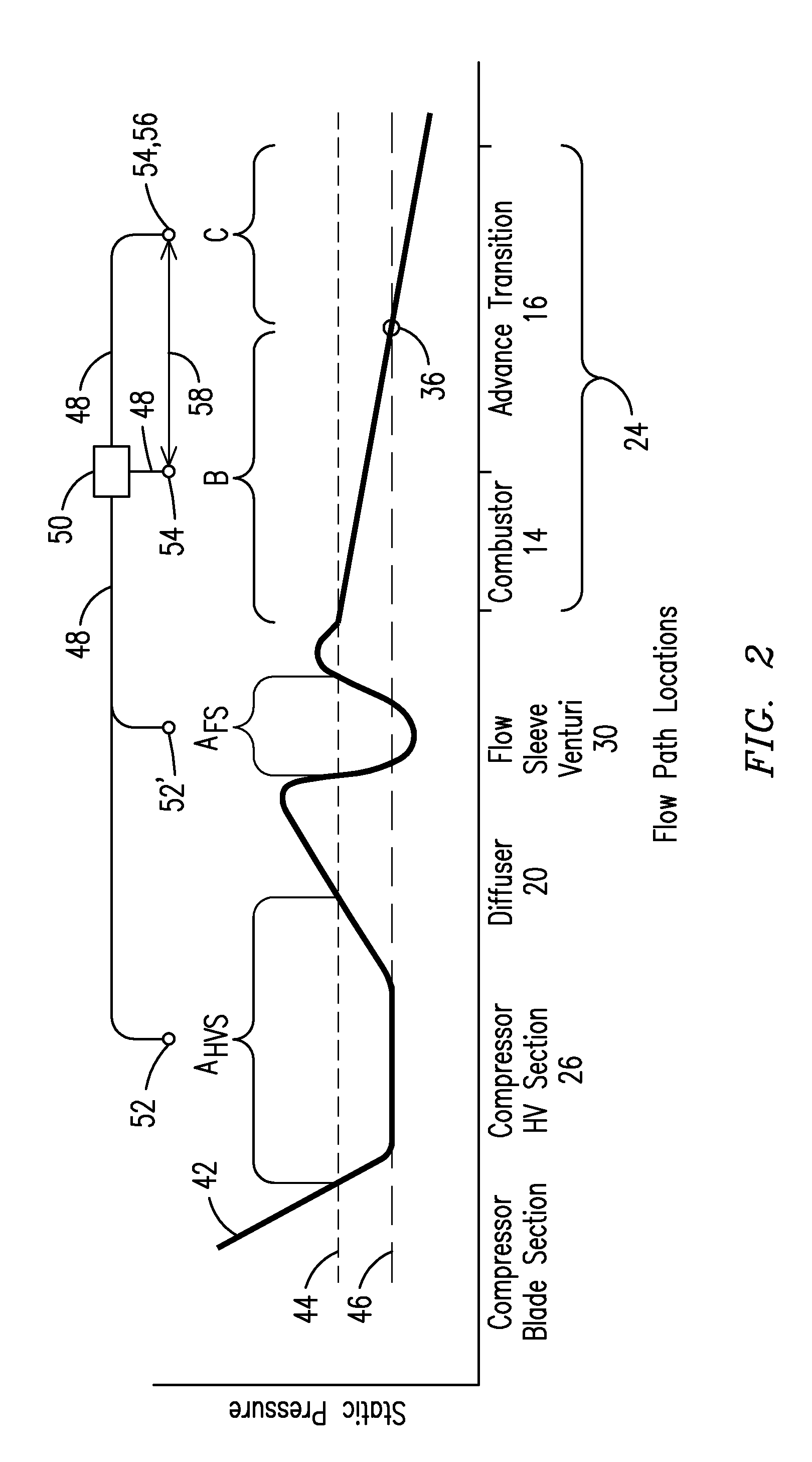
[0009]Fluids flowing through a gas turbine engine flow at varying speeds and as a result, these fluids experience varying static pressures throughout the gas turbine engine. As used herein, the term “fluids” includes compressed air up to the burner, and combustion gases from the burners on. The present inventors have recognized that in a conventional gas turbine engine with a combustor, a transition, and a first stage vane section, compressed air at a location upstream of the combustor may exhibit a static pressure below that of a static pressure of the combustion gases within the combustor and the transition. This may be so for combustion gases at any location along an entire length of the combustor and the transition.

[0010]In advanced transition designs a gas turbine engine may have an advanced design duct that directs the combustion gases from the combustor to the first row of turbine blades. The advanced design duct is configured to properly align the combustion gases and may co...


PUM


Abstract

An emissions control system for a gas turbine engine including a flow-directing structure (24) that delivers combustion gases (22) from a burner (32) to a turbine. The emissions control system includes: a conduit (48) configured to establish fluid communication between compressed air (22) and the combustion gases within the flow-directing structure (24). The compressed air (22) is disposed at a location upstream of a combustor head-end and exhibits an intermediate static pressure less than a static pressure of the combustion gases within the combustor (14). During operation of the gas turbine engine a pressure difference between the intermediate static pressure and a static pressure of the combustion gases within the flow-directing structure (24) is effective to generate a fluid flow through the conduit (48).

Description

STATEMENT REGARDING FEDERALLY SPONSORED DEVELOPMENT[0001]Development for this invention was supported in part by Contract No. DE-FC26-05NT42644, awarded by the United States Department of Energy. Accordingly, the United States Government may have certain rights in this invention.FIELD OF THE INVENTION[0002]The invention relates to an emissions control system for a gas turbine engine. More particularly, this invention relates to an emissions control system that utilizes differences in static pressure within the gas turbine engine to generate fluid flows that reduce the formation of oxides of nitrogen (NOx) and carbon monoxide (CO).BACKGROUND OF THE INVENTION[0003]High efficiency gas turbine engine combustors operate at high temperatures that may produce an unacceptable level of NOx emissions. One technique for reducing the formation of NOx includes recirculating a portion of the spent combustion gases back into the combustor. The presence of the recirculated vitiated gases reduces th...

Claims


Application Information

Patent Timeline
Patent Type & Authority Patents(United States)
IPC IPC(8): F02C7/08F02C1/00
CPCF23R3/42F23R3/26F23C9/08
Inventor LASTER, WALTER R.SCHILP, REINHARDWIEBE, DAVID J.
Owner SIEMENS ENERGY INC
Features
  • R&D
  • Intellectual Property
  • Life Sciences
  • Materials
  • Tech Scout
  • Unparalleled Data Quality
  • Higher Quality Content
  • 60% Fewer Hallucinations
Learn More