Connector

a technology of connecting rods and connectors, applied in the direction of coupling device connections, coupling protective earth/shielding arrangements, electric discharge lamps, etc., to achieve the effects of strong welding fastness, reduced impedance, and increased electric shielding

Active Publication Date: 2015-02-24
EZCONN
View PDF19 Cites 20 Cited by
  • Summary
  • Abstract
  • Description
  • Claims
  • Application Information

AI Technical Summary

Benefits of technology

[0013]The invention is further directed to provide a wire-side connector, which can keep geometry, a relative distance and position, and a dimension of each discrete core wire of a cable wire in a stable state, so as to enhance the stability of signal transmission.
[0031]According to an embodiment of the invention, the elastic contacting arm is configured with a cutting groove along a longitudinal direction thereof, so as to divide the elastic contacting arm into a first side elastic contacting arm and a second side elastic contacting arm. The quantity of contact points between the metal inner shell and the metal outer shell is increased accordingly, so as to reduce the impedance and increase the electric shielding effect.

Problems solved by technology

However, the above-described conventional wire-side connector has the following disadvantages in structure: (1) the buckle piece of the above-described conventional wire-side connector is the buckle piece with a single supporting point, which means that one end of the buckle piece is connected to the top surface of the plastic case, and the other end of the buckle piece is suspended, the structural strength of this type of the buckle piece with the single supporting point is fragile and easy to be damaged, and a bonding strength between the buckle piece with the single supporting point and the buckle hole of the board-side connector is also weak; (2) for each discrete core wire between the end portion of the cable wire and the transmission main body, no object is configured to carry and fix these discrete core wires, and geometry, relative distance, position and dimension of each discrete core wire are presented in an unstable state as the buckle piece with the single supporting point is suspended, which affects the stability of signal transmission; (3) an accommodating space of the plastic case is fixed and only cable wires with a single wire diameter can be received therein, which limits select and use of cable wires with different wire diameters; and (4) the entire plastic case is a plastic injection molded member made of the same material, and for convenience of plugging with the board-side connector, the plastic case is usually a rigid plastic case, which means a plugging end (for plugging with the board-side connector) and a cable wire jointing end (for fixing the end portion of the cable wire) respectively located at two ends of the plastic case both are rigid plastic materials, while the rigid cable wire jointing end will limit a winding curvature of the cable wire, which relatively increases the space occupied by the cable wire and the wire-side connector thereof.
However, the above-described conventional board-side connector has the following disadvantages in structure: (1) the conventional board-side connector only has the metal outer shell as a single layer of electric shielding structure, and a shielding effect for the external electromagnetic wave is not perfect; (2) the elastic contacting arm of the conventional board-side connector is contacted with the metal outer shell at a single position, and the number of contact points thereof is small and an impedance cannot be reduced effectively, so that an electric shielding effect of the metal outer shell is affected; (3) the multiple welding feet of the metal outer shell are welded to the circuit board in a single shaft flat direction, and the single shaft welding cannot provide a strong bonding force between the metal outer shell and the circuit board, which is not sufficient for resisting pulling, pushing and twisting forces when the wire-side connector is plugged into or out from the board-side connector, so that stability of an electrical contact between two connectors is affected.
The applicability of the conventional board-side connector and the conventional wire-side connector are poor due to the above reasons.

Method used


Image

  • Connector
  • Connector
  • Connector

Examples


Embodiment Construction

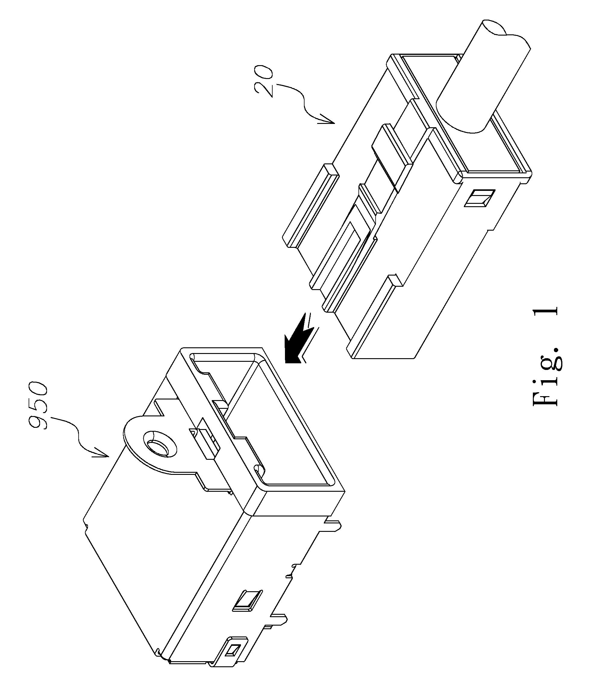
[0055]Referring to FIG. 1, the invention discloses to a connecting structure, wherein the connecting structure comprises a board-side connector 950 and a wire-side connector 20 plugged with the board-side connector 950. The foregoing and other technical contents, features and functions of the invention will be clearly presented in the following detailed description of the embodiments with reference to the accompanying drawings.

Board-side Connector

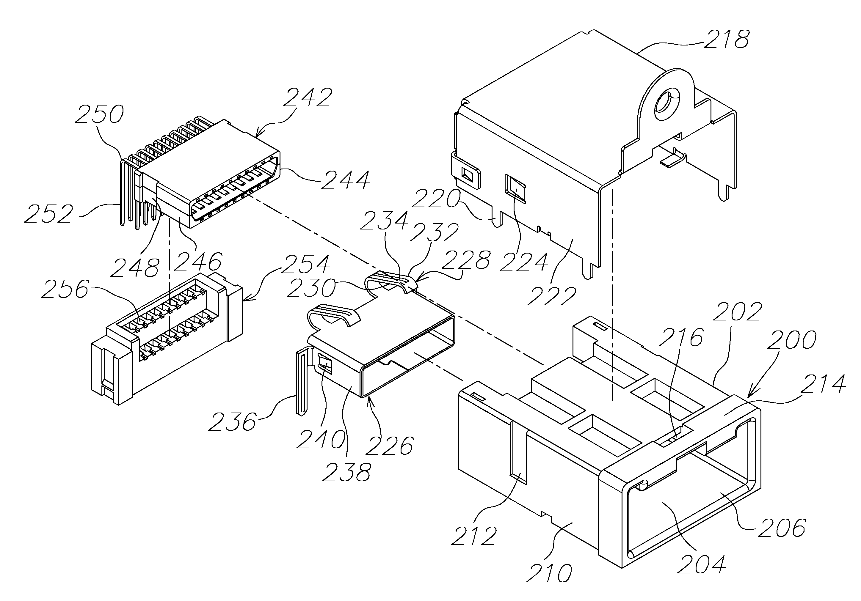
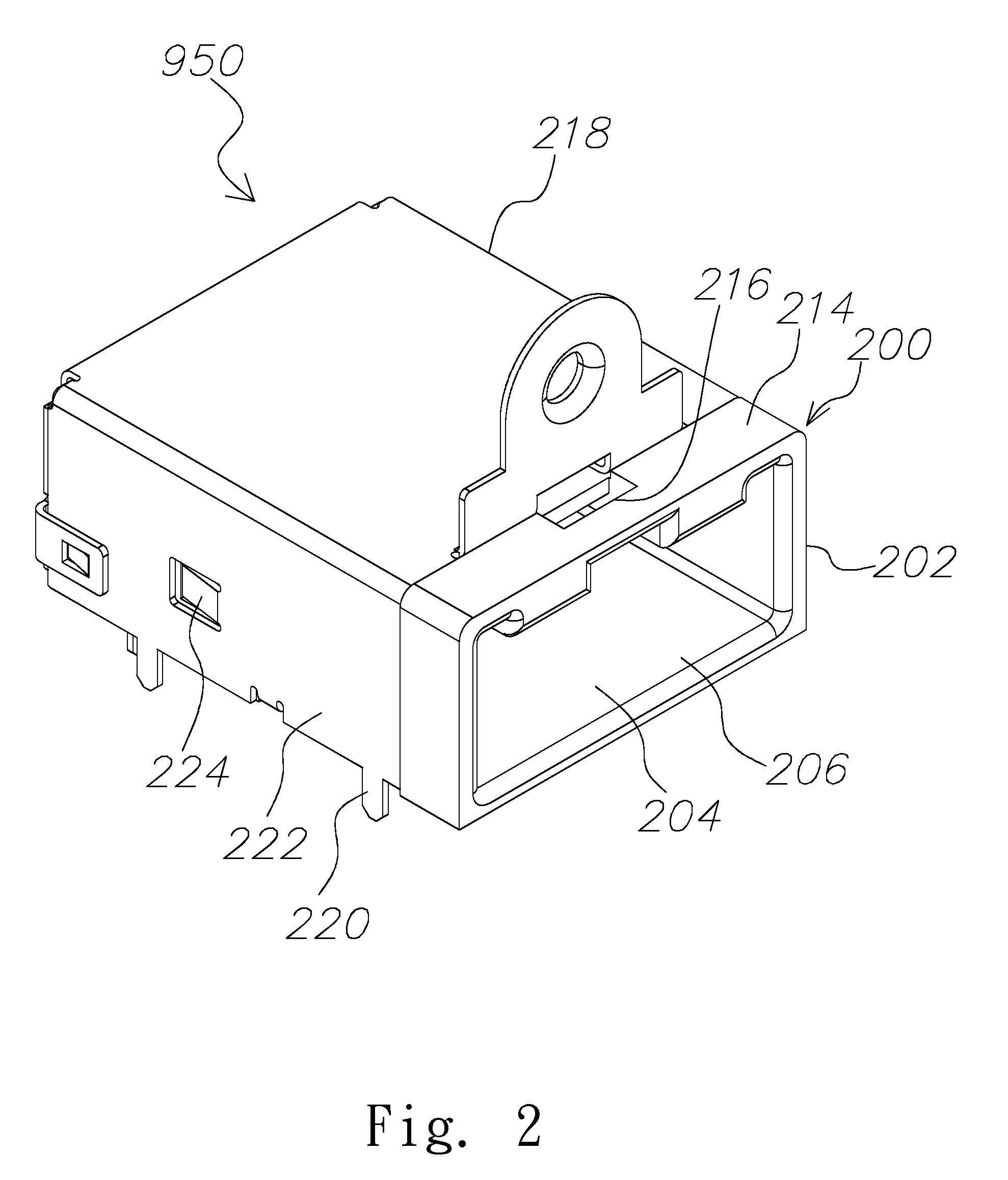
[0056]Referring to FIGS. 2 to 6, two perspective views, an exploded view, a sectional view and a schematic mounting view of the board-side connector 950 according to an embodiment of the invention are illustrated. As shown by the drawings, the board-side connector 950 according to an embodiment of the invention includes a plastic frame pedestal 200, a metal outer shell 218, a metal inner shell 226, a transmission main body 242 and a retainer 254.

[0057]The transmission main body 242 has a plastic frame 244 and multiple terminals 250 inserted...


PUM


Abstract

A connecting structure comprises a board-side connector and a wire-side connector. The board-side connector comprises a frame pedestal surrounding an accommodating chamber; a metal outer shell covering the exterior of the frame pedestal; a metal inner shell mounted to a mounting hole at a rear end of the accommodating chamber; and a transmission main body mounted to an interior of the metal inner shell. The wire-side connector comprises a transmission main body having multiple terminals having multiple first ends soldered to discrete core wires of a wire cable and multiple second ends configured to contact terminals of the board-side connector; a clamp cage at a rear side of the transmission main body; and a plastic case surrounding an accommodating chamber, wherein the accommodating chamber receives second ends of the terminals.

Description

RELATED APPLICATIONS[0001]This application claims priority to Taiwan Application Serial Number 101219195, filed Oct. 4, 2012 and Taiwan Application Serial Number 101219197, filed Oct. 4, 2012, which are incorporated herein by reference in their entireties.BACKGROUND[0002]1. Technical Field[0003]The invention relates to a connecting structure. More particularly, the invention relates to a board-side connector mounted onto a circuit board and a wire-side connector plugged with the board-side connector.[0004]2. Description of Related Art[0005]A wire-side connector is mounted to an end portion of a cable wire and configured for plugging with a corresponding board-side connector mounted to a circuit board of one electrical appliance, so as to achieve mutual transmission of electric power and signal between the cable wire and the electrical appliance.[0006]A conventional wire-side connector primarily includes a transmission main body, and a metal shell and a plastic case that cover the ex...

Claims


Application Information

Patent Timeline
Patent Type & Authority Patents(United States)
IPC IPC(8): H01R13/648H01R9/03H01R12/71H01R13/627H01R13/6593H01R13/6594H01R24/60H01R107/00
CPCH01R12/716H01R9/032H01R13/6272H01R13/6593H01R13/6594H01R24/60H01R2107/00Y10S439/942H01R13/65912
Inventor CHOU, HUNG-CHIH
Owner EZCONN
Why Eureka
Try Eureka