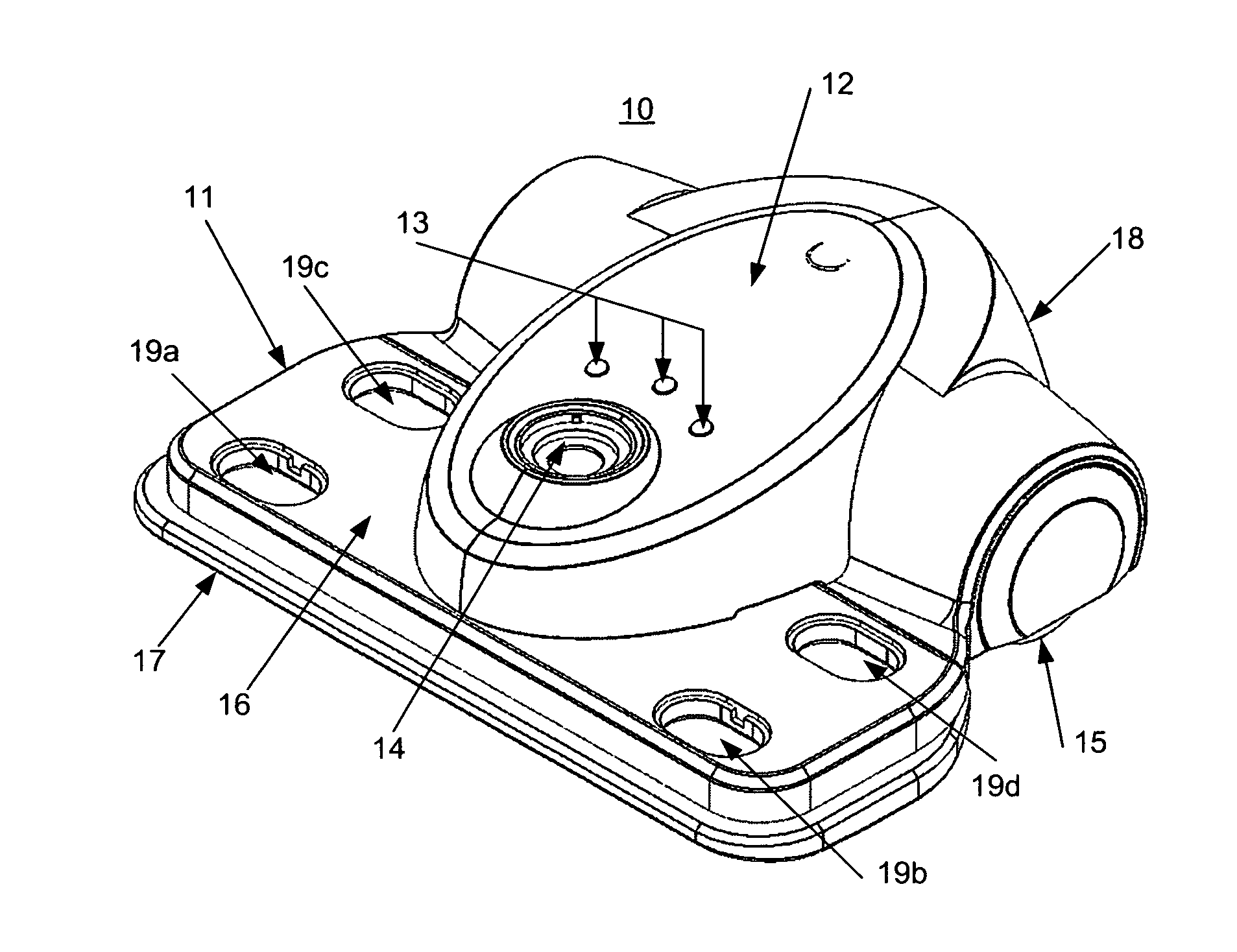
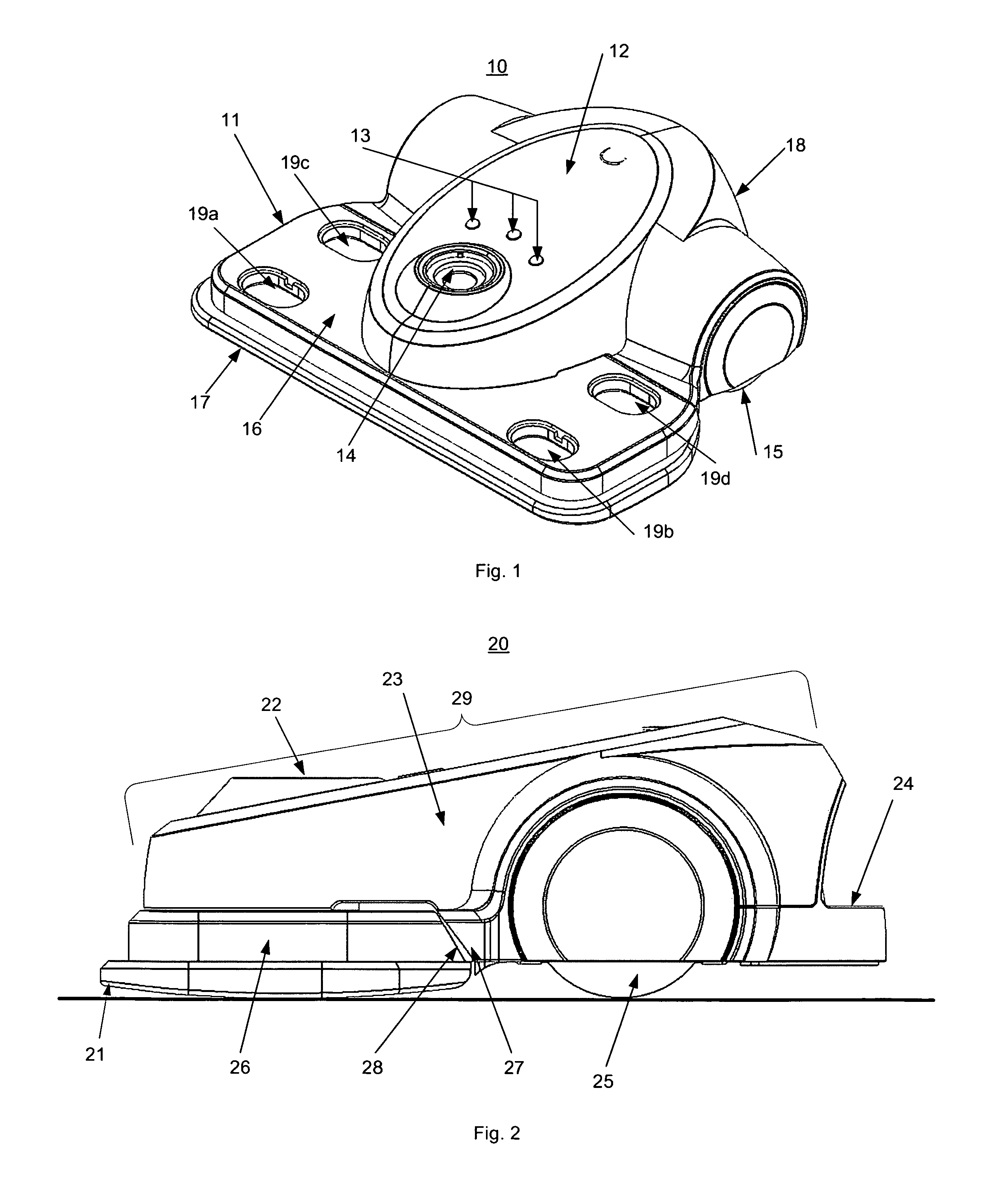
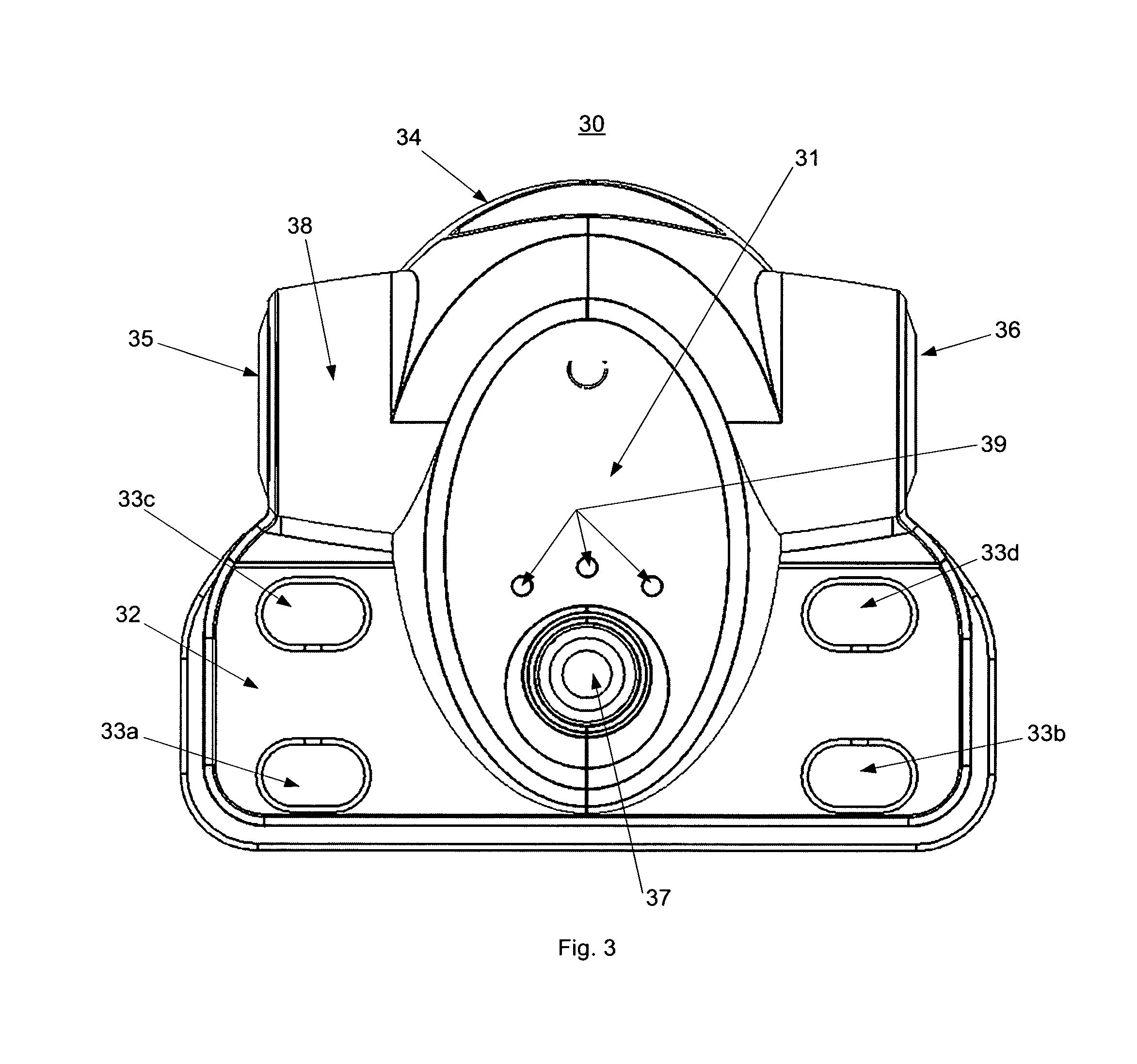
The down-side of the presently available solution for the mobile robotic platform is that the current configurations limit the size, reach and effectiveness of the cleaning mechanism.
Given that the dominant platform shape is circular for most robotic floor cleaners, the cleaning apparatus necessarily has be narrower than the robot itself, cover a smaller area of the floor relative to the size of the overall robot, and is not able to directly reach all the way to walls and into corners.
The small side
spinning brush attempts to draw debris into the path of the cleaning apparatus, although this has limited effectiveness and often needs to be replaced due to wear.
The typical placement of the wheels and casters to support a circular robot platform places additional constraints on the cleaning mechanism.
As one limitation, the cleaning mechanism can not extend to an area where there is a wheel or
caster, further limiting its size and configuration.
However, the extended reach of its cleaning abilities works only when the cleaning robot turns in place to “sweep” along the
radius of the turn.
While the “
appendage” approach provides a beneficial supplementary function for catching extra
dirt and dust, this approach does not overcome the limitation of the primarily cleaning mechanism being placed within the
footprint of the
mobile robot platform.
The limitation of this design is the larger size and longer shape of the combined form factor, which limits how well the robot would be able to navigate in tighter spaces.
However, the extended length of the cleaning robot would provide challenges for turning in tighter spaces, as well as for getting in and out of cluttered environments, such as between chair and table legs which are clustered together.
However, this configuration would still have the same limitations of navigating in tight spaces given the overall length and distance from the wheels to the cleaning pad.
This robotic cleaner design offers a greater degree of flexibility for cleaning in different spaces, but comes at a price of significantly more cost and complexity.
Specifically, this robotic cleaner design includes more
moving parts and more sensors to judge situational conditions and control the position of the cleaning mechanism, so this will likely result in a physically larger robot.
While this may be appropriate for a commercial robotic cleaner for large office and commercial spaces, this disclosed cleaning
robot design would not fit the requirements of a
consumer robotic cleaner needing to clean in tight spaces, such as around a kitchen table that is positioned close to one or more walls, which also includes a number of chairs, as well as in places deep under low furniture.
This is primarily because in the past there has not been an effective and low-cost navigation solution that can track the robot's position and guide it to intelligently cover the desired area for cleaning the floor.
This approach has several major limitations.
First, the robot must clean for very long periods of time to reach
full coverage of a room or other designated area of a home.
As more area of the room or area of the home is covered, the
random method works against the robot, as the robot spends proportionally more and more time cleaning areas it has already cleaned.
This approach has the benefit of
filling in more area in different locations and improving the efficiency curve relative to a pure random approach, but the same core dynamic exists in terms of making the robot becoming increasing inefficient as more of the room is covered.
As another limitation, cleaning strategies that are described as random or semi-random do not normally result in a random distribution of cleaning coverage across a typical room or area of a home.
However, rooms and areas in homes are not empty, and instead have a variety of interior obstacles which the robot must navigate around.
Rather, large obstacles, namely furniture, are clustered together and form uneven barriers of entry for a robot to navigate through.
However, this process takes time for enough permutations to take place and for a large percent of those permutations, the robot may be frequently blocked and / or deflected away from areas occupied by these obstacles.
This often causes the robot to significantly overclean some areas of the room or areas of the home while under cleaning other areas.
This results in poor cleaning of those areas, inefficient use of energy, as well as excess wear on the robot and potentially of the
floor covering in the over-cleaned areas.
These limitations of a random or semi-random approach, the general low efficiency in reaching all areas of the floor, and the systematic pattern of repeatedly missing certain parts of the floor area, are counter-productive to the primary cleaning function of the robot.
The challenge with systematic cleaning patterns is that the structure of the pattern may be too rigid to adapt enough for successfully covering all areas in a complex environment.
While a random cleaning strategy over time will allow the robot to find its way almost everywhere just by chance, although not efficiently or with equal success, a systematic strategy alone can not guarantee
full coverage.
The problem is the pattern generally has one preferred direction and follows rules about which way to proceed when it has multiple directions to select from.
To date, very few systems have been developed that would be suitable for a home cleaning robot.
As one example, the Samsung® Hauzen® vacuum cleaning robot uses a camera to create a map of where it cleans to provide some of these functions, but this product requires complex image recognition
software and more expensive sensors and internal computing hardware built into the robot.
To date, this product is significantly more expensive than even the premium version of the leading models for robotic floor cleaners, and accounts for a very small share of the market.


