Hard disk rack

a hard disk rack and rack technology, applied in the field of racks, can solve the problems of poor expandability and flexibility of conventional chassis kits, inconvenient storage, and inability to fit a 1u server, and achieve the effects of convenient stacked and stored conveniently, reduced development cost of manufacturing molds, and convenient us

Active Publication Date: 2015-02-24
GIGA BYTE TECH CO LTD
View PDF31 Cites 8 Cited by
  • Summary
  • Abstract
  • Description
  • Claims
  • Application Information

AI Technical Summary

Benefits of technology

[0017]The effect of the present invention is achieved in the following way. A number of the cartridges of the hard disk rack can be selected as desired, and the cartridges can be assembled in the housing simply and quickly without cumbersome procedures, such that the hard disk rack is very convenient and efficient in use. Meanwhile, the cartridges can be assembled in different specification of the housing of the hard disk rack because the cartridges are stackable, such that the development cost of the manufacturing mold can be reduced, because there is no need to develop different type of the manufacturing mold for the cartridges with different specification. Moreover, because the appearance of the cartridges is identical, the cartridges can be stacked and stored conveniently, for utilizing the storage space effectively.

Problems solved by technology

A 2U chassis kit can not fit for a 1U server, confining the use of the chassis kit with a specific rack unit.
Particularly, the conventional chassis kit has poor expandability and flexibility and thus is not space-efficient, and it is undesirable to prepare chassis kits with different dimensions when dealing with limited space.

Method used


Image

  • Hard disk rack
  • Hard disk rack
  • Hard disk rack

Examples


first embodiment

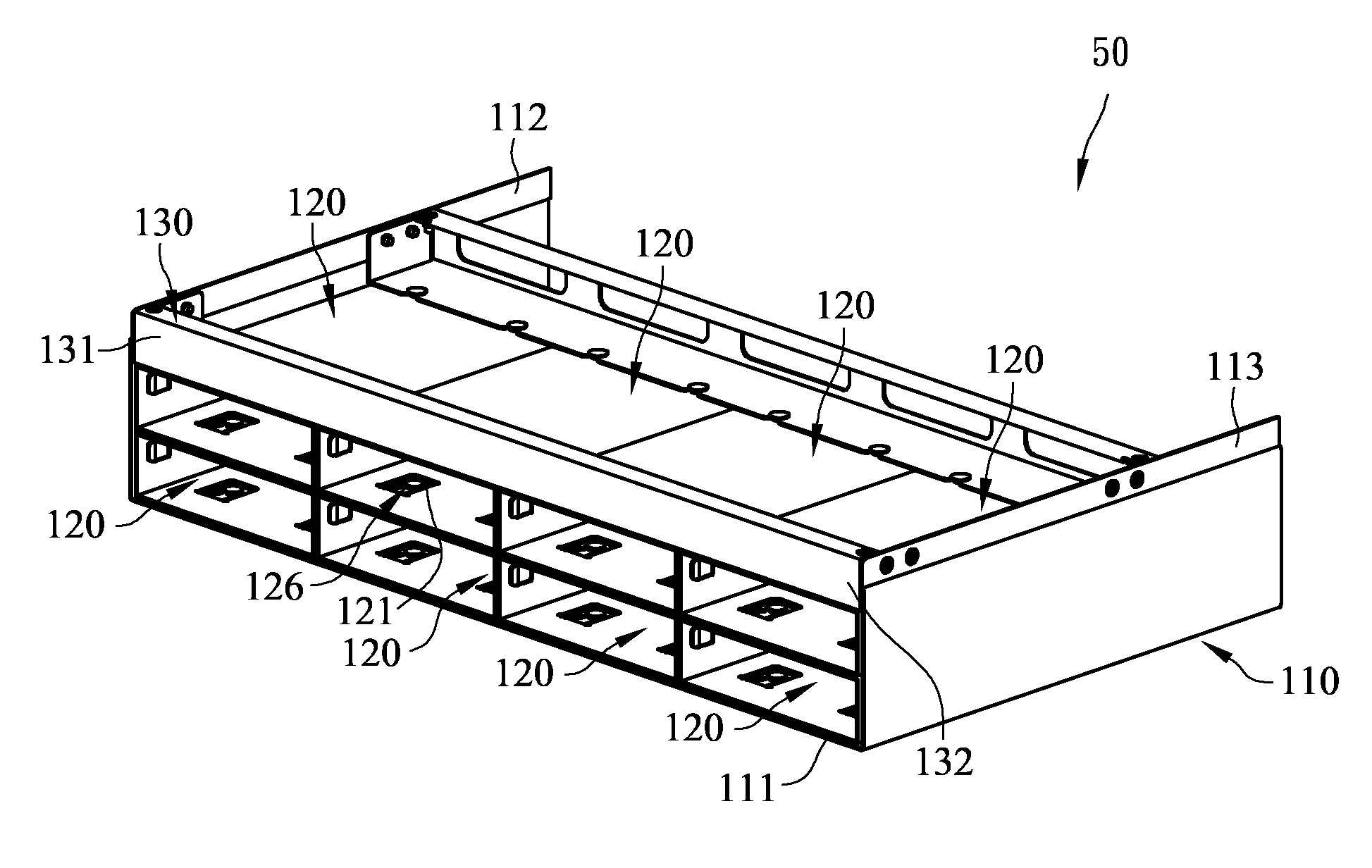
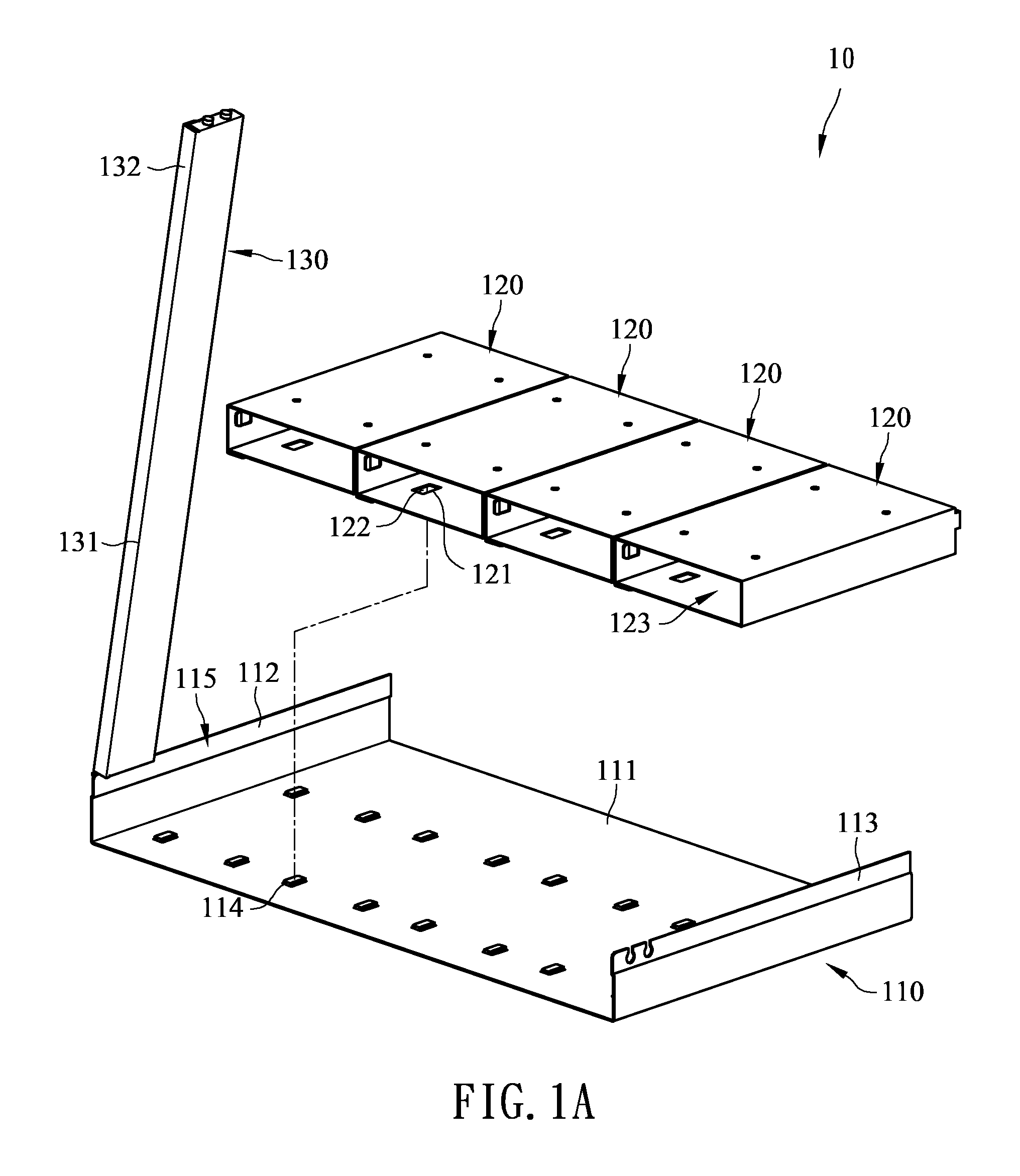
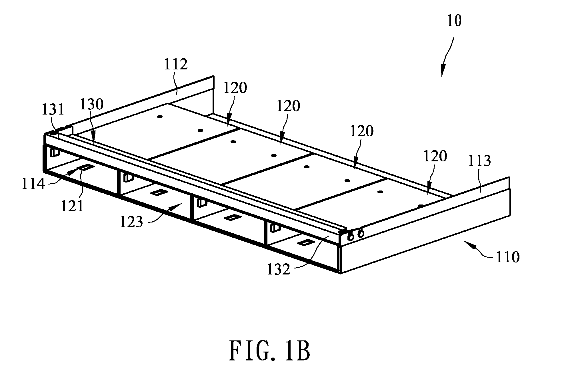
[0035]Referring to FIGS. 1A and 1B, a hard disk rack 10 of the present invention is used to assemble a plurality of hard disk modules, which comprises a housing 110, a plurality of cartridges 120, and a batten 130. The housing includes a bottom 111, a first sidewall 112 and a second sidewall 113, the bottom 111 is connected between the first and second sidewalls 112, 113, and provided with a plurality of positioning elements 114 which are arranged in spaced-apart disposition on the bottom 111. The first and second sidewalls 112, 113 are substantially perpendicular to the bottom 111, and an accommodating space 115 is defined between the bottom 111, the first sidewall 112 and the second side wall 113. The plurality of positioning elements 114 are located in the accommodating space 115, and may be, but not limited to, disposed at the bottom 111 and spaced apart from the first sidewall 112 to the second sidewall 113.

[0036]Each one of the cartridges 120 of the hard disk rack 10 is substa...

second embodiment

[0041]Referring to FIGS. 2A and 2B and 2C, are exploded and schematic assembly views and a lateral view of a hard disk rack respectively according to the present invention.

[0042]The hard disk rack 20 of the second embodiment of the present invention is similar to that of the first embodiment except that a number of a back circuit board 124. In the first embodiment, the hard disk rack 10 may be, but not limited to, further disposed a back circuit board 124 in the housing 110, and a plurality of electrical connectors are disposed on the back circuit board 124 corresponding to the plurality of the cartridges 120, such that the plurality of the hard disk modules can be electrically connected to the same back circuit board 124 via the electrical connectors after assembled in the cartridges 120.

[0043]However, in the second embodiment, each one of the cartridges 120 of the hard disk rack 20 are further provided with a back circuit board 124 and an electrical connector 125, wherein the back...

fourth embodiment

[0050]Referring to FIGS. 4A and 4B, a hard disk rack 40 of the present invention includes a housing 110, a plurality of cartridges 120, and two battens 130. The housing includes a bottom 111 provided with a plurality of positioning elements 114, and a first sidewall 112 and a second sidewall 113 which are respectively connected to opposite side of the bottom 111 and substantially perpendicular to the bottom 111 to define an accommodating space 115 therebetween, wherein the plurality of the positioning elements 114 are disposed on the bottom 111 in the accommodating space 115 and arranged in two rows and at intervals from the first sidewall 112 to the second sidewall 113. In addition, each positioning element 114 includes a support portion 1141 and a restricted portion 1142, the support portion 1141 is connected between the restricted portion 1142 and the bottom 111, and the width of the support portion 1141 is smaller than the width of the restricted portion 1142.

[0051]The plurality...


PUM

PropertyMeasurementUnit
speedaaaaaaaaaa
sizeaaaaaaaaaa
dimensionaaaaaaaaaa

Abstract

A hard disk rack comprises a housing, a plurality of cartridges for receiving a plurality of hard disk modules, and at least one batten. The housing has a bottom, and a plurality of positioning elements disposed on the bottom at intervals. The cartridges are detachably disposed on the bottom in stacks by fastening a fastening portion to the positioning elements of the housing. The batten is pressed against the cartridges for sandwiching the cartridges between the batten and the bottom of the housing, and two opposite ends of the batten are connected to two opposite sidewalls of the housing detachably in order to facilitate the assembly and disassembly of the cartridges conveniently.

Description

CROSS-REFERENCE TO RELATED APPLICATIONS[0001]This application claims the benefit of the filing date of Taiwan Patent Application No. 101126492, filed on Jul. 23, 2012, in the Taiwan Intellectual Property Office, R.O.C., the disclosure of which is incorporated herein in its entirety by reference.BACKGROUND OF THE INVENTION[0002]1. Field of the Invention[0003]The invention relates to a rack; more particularly, to a hard disk rack.[0004]2. Description of the Prior Art[0005]With development of the internet and increase of the internet bandwidth, more and more information may be processed over the network. Among others, remarkable advances have been made in cloud computing in recent years. The concept of the cloud computing is sharing software, resources and information through internet connection rather than having local servers or personal devices to handle applications.[0006]Generally, a server is used to provide more stable operating environment of the computer. By way of sever manag...

Claims


Application Information

Patent Timeline
Patent Type & Authority Patents(United States)
IPC IPC(8): H05K5/02G11B33/02G11B33/12
CPCG11B33/02H05K5/02G11B33/128
Inventor HOU, CHIN JENFU, HSIN TENGHUANG, CHI CHENLIU, HIS FENG
Owner GIGA BYTE TECH CO LTD
Why Eureka
Try Eureka