Frequency converter and wireless repeater using the same, and wireless repeating system using the same

a technology of wireless repeater and frequency converter, which is applied in the direction of pulse technique, transmission monitoring, instruments, etc., can solve the problems of cost of building the base station, the inability of both base-stations (bsb>1/b>, bsb>2/b>) to provide services, and the difficulty in using the frequencies being used by other wireless systems. to achieve the effect of downsizing the wireless repeater

Inactive Publication Date: 2015-02-24
HITACHI METALS LTD
View PDF10 Cites 0 Cited by
  • Summary
  • Abstract
  • Description
  • Claims
  • Application Information

AI Technical Summary

Benefits of technology

[0010]Since different terminals rarely exist at the same location in effect, the increase of terminals wanting to be provided with broadcast services means that areal density of the terminals becomes uniform. Under this condition, it is possible to cope with the increase of terminals wanting to be provided with broadcast services by locating many broadcast base-stations (BS) with small output. However, the number of RF cables used for delivering the contents to those many base-stations (BS) increases exponentially, which increases not only the geological area to be secured for building the base-stations but also the cost of building the base-station due to increased number of RF cables, thus becoming a serous problem.
[0015]The present invention enables signals received by a wireless repeater to be frequency-converted and transmitted via digital circuits without using an analog frequency converter comprising a mixer and a local oscillator, which is effective for down-sizing the wireless repeater.

Problems solved by technology

Since media that can be used for wireless broadcast is effectively limited electromagnetic waves, it is very difficult to use frequencies being used by other wireless systems.
However, if a base-station increases the transmission output, radio waves from the base-station also reach wireless terminal (TS) in the area where the radio waves did not reach until then, which makes it impossible for both base-stations (BS1, BS2) to provide services due to radio interference.
However, the number of RF cables used for delivering the contents to those many base-stations (BS) increases exponentially, which increases not only the geological area to be secured for building the base-stations but also the cost of building the base-station due to increased number of RF cables, thus becoming a serous problem.

Method used


Image

  • Frequency converter and wireless repeater using the same, and wireless repeating system using the same
  • Frequency converter and wireless repeater using the same, and wireless repeating system using the same
  • Frequency converter and wireless repeater using the same, and wireless repeating system using the same

Examples


embodiment 1

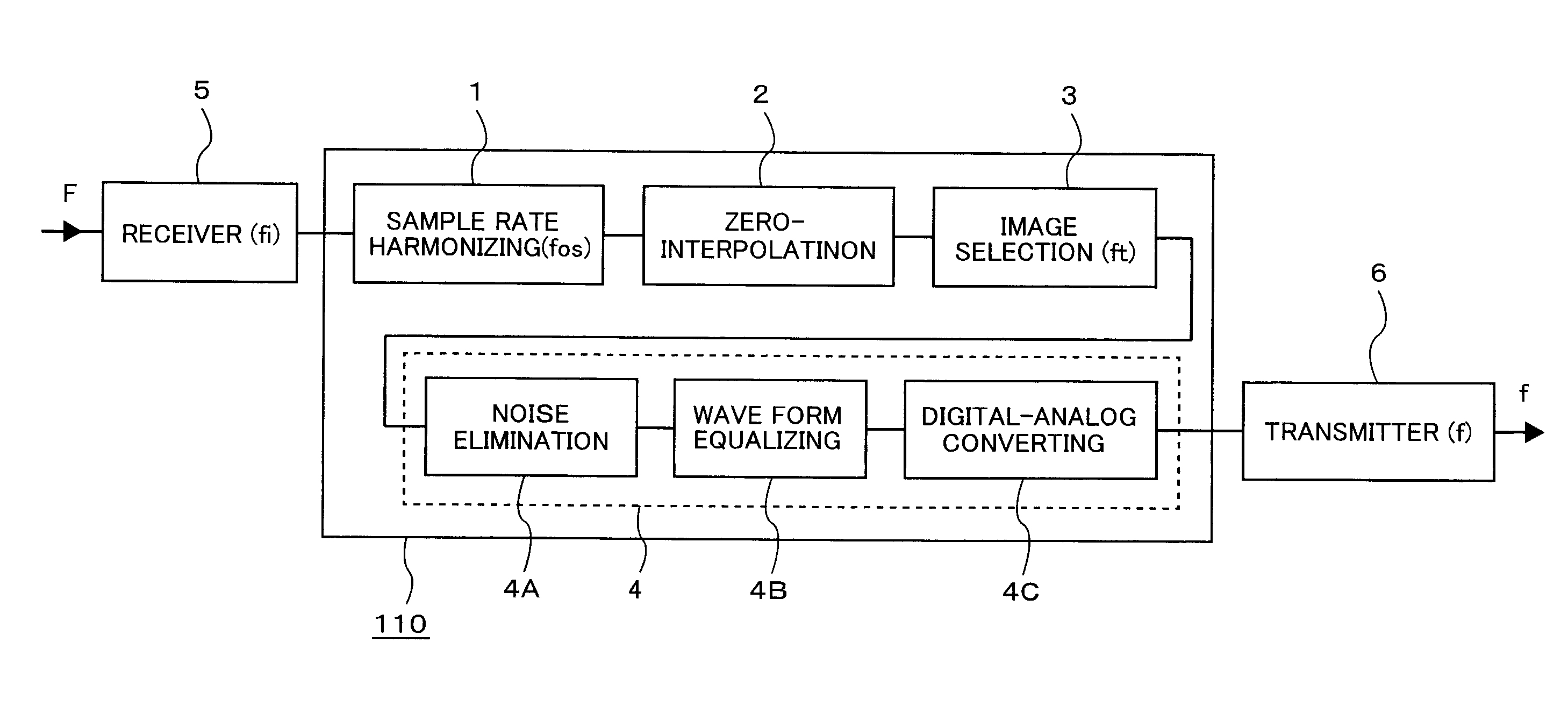
[0057]FIG. 1A is a diagram showing a configuration of a first embodiment of a frequency converter of the invention, and FIG. 1B shows an exemplary configuration of a wireless repeating system adopting the frequency converter of the first embodiment.

[0058]A frequency converter 110 includes a sample rate harmonizing circuit 1 (an oversampling unit), a zero-value interpolation circuit 2, an image selection circuit 3, and a digital-analog conversion unit 4, which are cascaded each other. The digital-analog conversion unit 4 includes a noise elimination capability 4A, a waveform equalizing capability 4B, and a DA conversion capability 4C. A first analog signal of reception frequency F is converted to a digital signal via a reception processing unit 5 (an original digital signal generation unit) and input to the frequency converter 110. That is, a first analog signal is digitally converted at a first sampling frequency (fi) to generate an original digital signal via an analog-digital conv...

embodiment 2

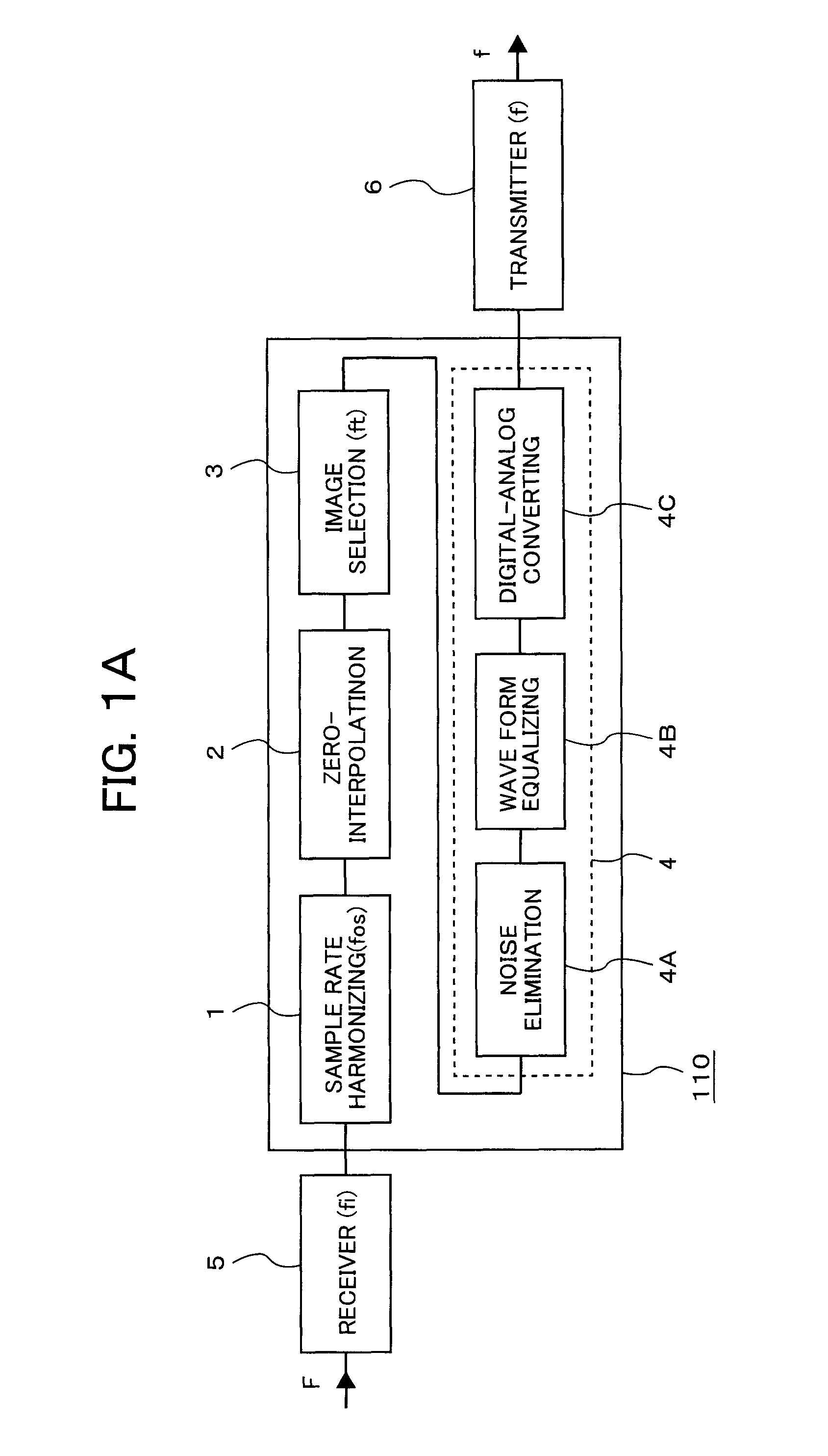
[0063]FIG. 2 is a diagram showing the second embodiment of a frequency converter of the present invention. This frequency converter differs from the frequency converter in FIG. 1A in that the digital-analog conversion unit 4 is replaced by a delta-sigma modulation circuit 7. The frequency converter 110 is composed of the sample rate harmonizing circuit 1, the zero-value interpolation circuit 2, the image selection circuit 3, and the delta-sigma modulation circuit 7, which are cascaded each other. An original digital signal of frequency F input to the sample rate harmonizing circuit 1 forms plural data points between the signal sequence of time axis, zero data is defined at the plural data points by the zero-value interpolation circuit 2, and as many as a multiple of sample rate of spectrums are reproduced that have the same shape of the spectrum of the original digital signal. Out of these plural image digital signals, a specific one is extracted by the frequency axis image selectio...

embodiment 3

[0065]FIG. 3 is a diagram showing an exemplary configuration of a wireless repeater of a third embodiment of the present invention. The wireless repeater 102 includes a receive antenna 10, a low-noise amplifier 11, a high rejection filter 12, an analog-digital converter (ADC) 13, a frequency converter 110, a low pass filter 17, a power amplifier 18, and a transmit antenna 20, which are cascaded. The frequency converter 110 includes an oversampler 14, a band-pass filter 15, and a delta-sigma type digital-analog converter 16, which are cascaded. In this embodiment, the frequency conversion delta-sigma conversion circuit 7 of the second embodiment is used for the delta-sigma type digital-analog converter 16.

[0066]A first analog signal input from the receive antenna 10 is amplified by the low-noise amplifier 11, unwanted high-frequency components are eliminated form the signal in order to prevent the generation of an alias that hinders digital-analog conversion when analog-digital conve...


PUM


Abstract

According to a wireless repeating system of the invention, a first analog signal is digitally converted at a first sampling frequency, a converted original digital signal is oversampled at a second sampling frequency higher than the first sampling frequency, an image digital signal occupying a specific frequency band out of plural image digital signals generated by zero-interpolation is extracted via a digital filter, and the image digital signal is input to a delta-sigma demodulator to convert to a second analog signal and output the second analog signal.

Description

CLAIM OF PRIORITY[0001]The present application claims priority from Japanese Patent Application JP 2010-277895 filed on Dec. 14, 2010, the content of which is hereby incorporated by reference into this application.FIELD OF THE INVENTION[0002]The present invention relates to a frequency conversion circuit, a wireless repeater using the same, and a wireless repeating system using the same, and specifically relates to frequency conversion technology suitable for implementing a wireless signal repeater wherein the frequency of receive signal carriers and the frequency of transmit signal carriers are different when repeating wireless signals in a narrow area broadcasting system or the like.BACKGROUND TECHNOLOGY OF THE INVENTION[0003]In stead of analog broadcasting that broadcasts contents with wireless signals in which analog modulation is applied to the contents, digital broadcasting that broadcasts contents with wireless signals in which digital modulation is applied to the contents st...

Claims


Application Information

Patent Timeline
Patent Type & Authority Patents(United States)
IPC IPC(8): H04L25/52G06T1/00G06T3/40H03D7/00H03D7/18H04B1/40H04B7/15H04B7/155H04W16/26
CPCG06T1/00G06T3/40H04B7/155
Inventor TAKEI, KEN
Owner HITACHI METALS LTD
Why Eureka
Try Eureka