Cutting apparatus

a cutting device and cutting blade technology, applied in the direction of thrusting weapons, white arms/cold weapons, weapons, etc., can solve the problems of pins or small axles easily breaking, locking mechanisms failing to operate, and weak structure, etc., to facilitate the rotation of the cutting blad

Inactive Publication Date: 2015-03-03
LAU PING SUN
View PDF3 Cites 2 Cited by
  • Summary
  • Abstract
  • Description
  • Claims
  • Application Information

AI Technical Summary

Benefits of technology

[0010]An object of the present invention is to provide a cutting apparatus which comprises a blade rotation arrangement for facilitating rotation of a cutting blade in a secure and convenient manner.

Problems solved by technology

There exist a number of disadvantages in associated with this conventional rotating knife, these disadvantages will be discussed below with reference to U.S. Pat. No. 7,124,510 to Frazer.
This structure is very weak in strength, especially when the lock pin is pivotally moved to lock and unlock the blade and is itself carried by a small axle.
When the rotating knife has been used for a prolonged period of time, the lock pin or the small axle may break easily and the locking mechanism will fail to operate.
Again, it is rather easy for this pivotal mechanism of the lever to fail, especially when the rotating knife is used in extreme conditions, such as in outdoor environment during hiking, camping, or even in outdoor work.
As a result, when the elasticity of that spring looseness, the lever may accidentally disengage from the blade and the blade is accidentally unlocked.
This imparts potential safety issues for the knife disclosed in '510 patent.
If the blade is not properly orientated but the user erroneously determines that the blade is in the proper orientation, such as aligning with the handle, the cutting performance of the knife will be affected.

Method used


Image

  • Cutting apparatus
  • Cutting apparatus
  • Cutting apparatus

Examples


Embodiment Construction

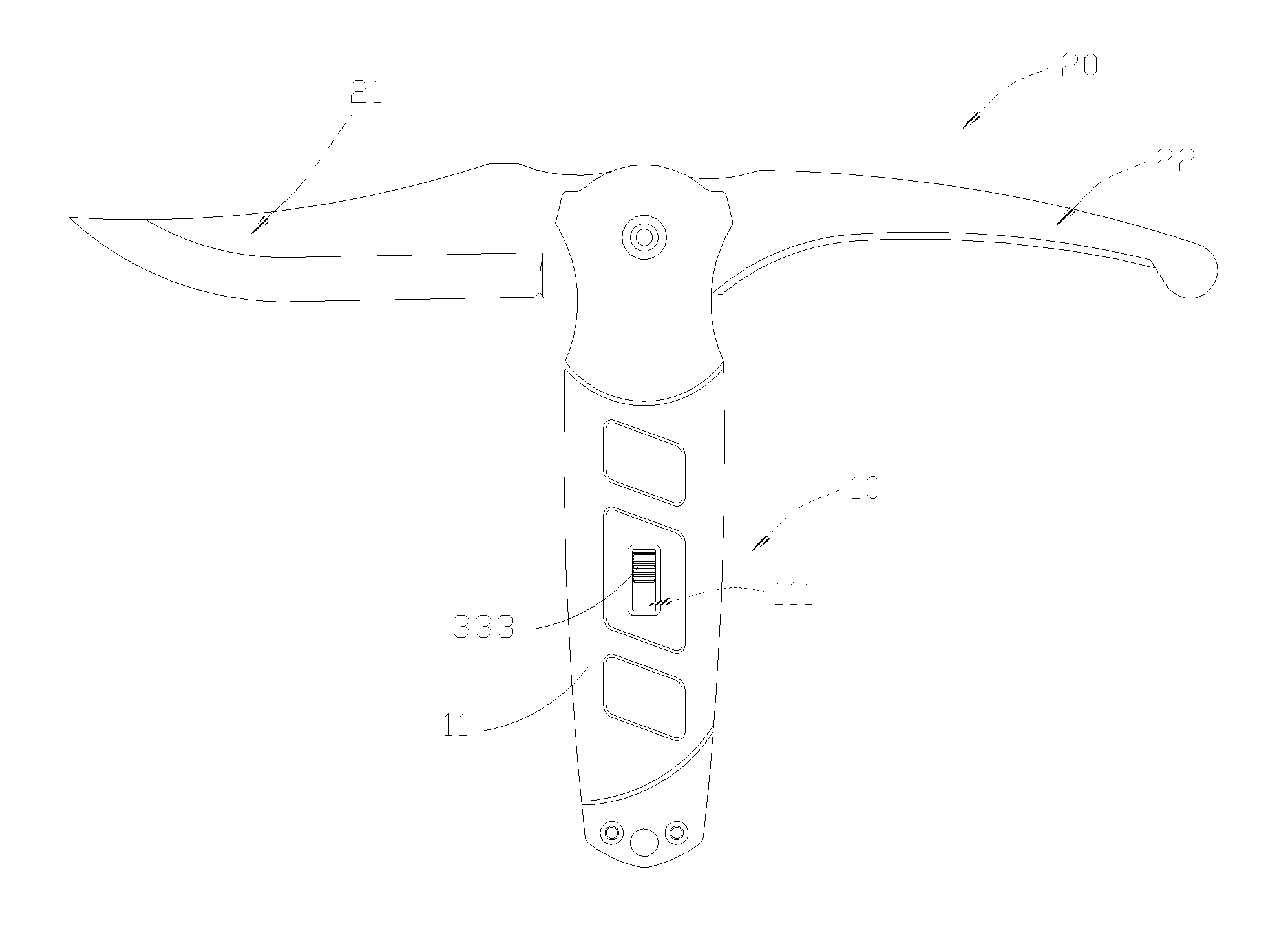
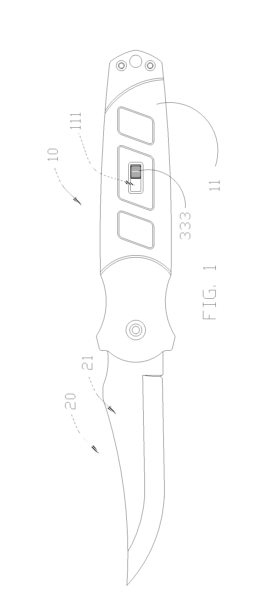
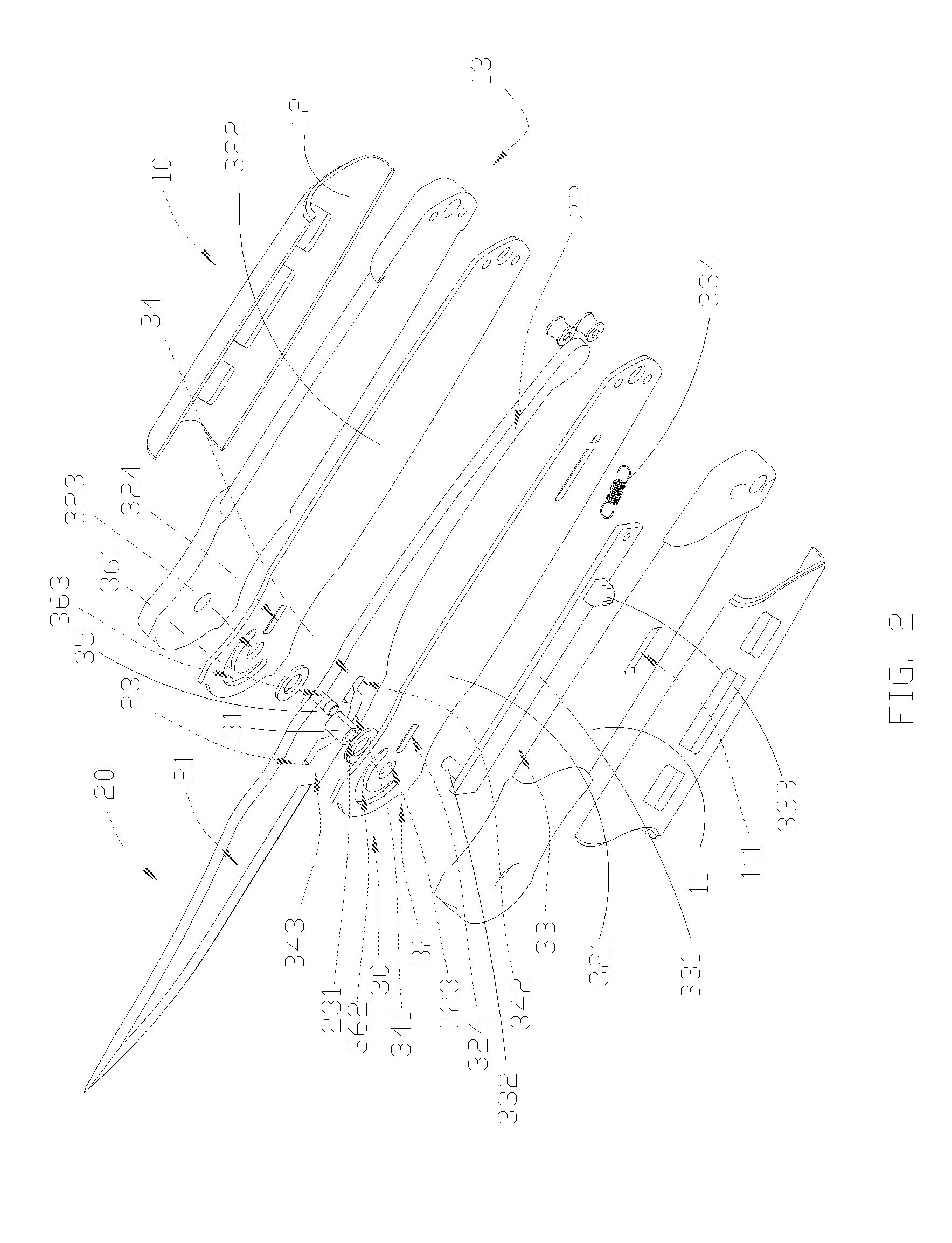
[0039]Referring to FIG. 1 to FIG. 5 of the drawings, a cutting apparatus according to a preferred embodiment of the present invention is illustrated, in which the cutting apparatus comprises a handle frame 10, a cutting blade 20, and a blade rotation arrangement 30.

[0040]The handle frame 10 comprises a first elongated handle member 11 and a second elongated handle member 12 mounted to the first elongated handle member 11 to form a receiving cavity 13 between the first elongated handle member 11 and the second elongated handle member 12.

[0041]The cutting blade 20 has a first blade portion 21, a second blade portion 22, and a mid blade portion 23 extended between the first blade portion 21 and the second blade portion 22, wherein the cutting blade has a length longer than that of the handle frame 10.

[0042]The blade rotation arrangement 30 comprises a pivot member 31, a securing frame 32 and an actuation member 33. The pivot member 31 is extended from the handle frame 10 to connect to ...


PUM


Abstract

A cutting apparatus includes a handle frame, a cutting blade, and a blade rotation arrangement. The cutting blade has a first blade portion and a second blade portion. The blade rotation arrangement includes a pivot, a securing frame and an actuation member. The cutting blade is arranged to rotate between a first position and a second position, wherein in the first position, the first blade portion is extended out of the receiving cavity while the second blade portion is received in the receiving cavity, wherein in the second position, the second blade portion is extended out of the receiving cavity while the first blade portion is received in the receiving cavity. The securing frame is mounted in the receiving cavity for reinforcing the cutting blade when the cutting blade move between and at the first position and the second position.

Description

BACKGROUND OF THE PRESENT INVENTION[0001]1. Field of Invention[0002]The present invention relates to a cutting apparatus, and more particularly to a cutting apparatus comprising a blade rotation arrangement for facilitating rotation of a cutting blade in a secure and convenient manner.[0003]2. Description of Related Arts[0004]A conventional cutting apparatus, such as a rotating knife, an elongated handle having supporting cavity formed therein, and an elongated blade rotatably supported in the supporting cavity for rotatably extending out of the elongated handle to cut a desirable object. The elongated blade usually has two opposed end portions crafted and designed to accomplish two different cutting purposes. For example, one end portion of the elongated blade may have a regular cutting blade while the other end portion has a plurality of teeth formed thereon so as to allow a user to use it as a mini saw.[0005]This kind of conventional rotating knife usually has an actuation device...

Claims


Application Information

Patent Timeline
Patent Type & Authority Patents(United States)
IPC IPC(8): B26B1/04
CPCB26B1/048B26B9/00
Inventor LAU, PING SUN
Owner LAU PING SUN
Why Eureka
Try Eureka