
Expiratory valve of an anesthetic breathing apparatus having safety backup

a technology of safety backup and anesthetic breathing, which is applied in the direction of lift valves, functional valve types, medical devices, etc., can solve the problems of limiting the life of the operating unit, low accuracy of the adjusted pressure limit, and impaired function of such mechanical apl valves, so as to achieve accurate and flexible control of the adjustable valve

Active Publication Date: 2015-03-03
MAQUET CRITICAL CARE
View PDF35 Cites 0 Cited by
  • Summary
  • Abstract
  • Description
  • Claims
  • Application Information

AI Technical Summary

Benefits of technology

The patent aims to provide a valve, apparatus, and method for anesthetic breathing that overcomes the limitations of existing art. It allows for better control of pressure limiting, flexible adjustments during electrical faults, and reduces maintenance requirements. The valve operating unit has a long service life without the need for servicing or replacement of parts. These technical effects provide for improved reliability and flexibility of anesthetic breathing equipment.

Problems solved by technology

In addition, it is sometimes desired during mechanical ventilation that the operator wants to switch over to a phase of manually controlled ventilation in order to check the condition of the patient, for example in connection with a change in the composition of an anesthetic gas.
However, the function of such mechanical APL valves may be impaired by a disadvantageously low accuracy of the adjusted pressure limit, as well as an inertial delay during opening.
Furthermore, the mechanical construction of the valve operating unit is subject to wear and tear, which on the one hand limits the life of the operating unit, and which on the other hand leads to an undesired variation of the adjustment mechanism over time.
This contributes to an accelerated wear of the APL valve mechanism.
Moreover, such mechanical APL valves may be slow in operation.
In addition, costs arise for unmounting and disassembling such mechanical APL valves for a necessary cleaning and / or disinfection, e.g. by autoclaving the APL valves, as well as a subsequent re-assembly of the APL valve parts and re-mounting into the anesthesia breathing apparatus.
Hence, APL valves are traditionally components in anesthesia breathing apparatuses, which are cause of a number of issues that need to be eliminated.
However, a drawback of such electronically controlled and operated APL valves is that these do not operate at power failure.
These type of APL valves is superior to mechanical APL valves, but they are dependent on an electrical power supply, which may result in a potential safety issue at power failure.
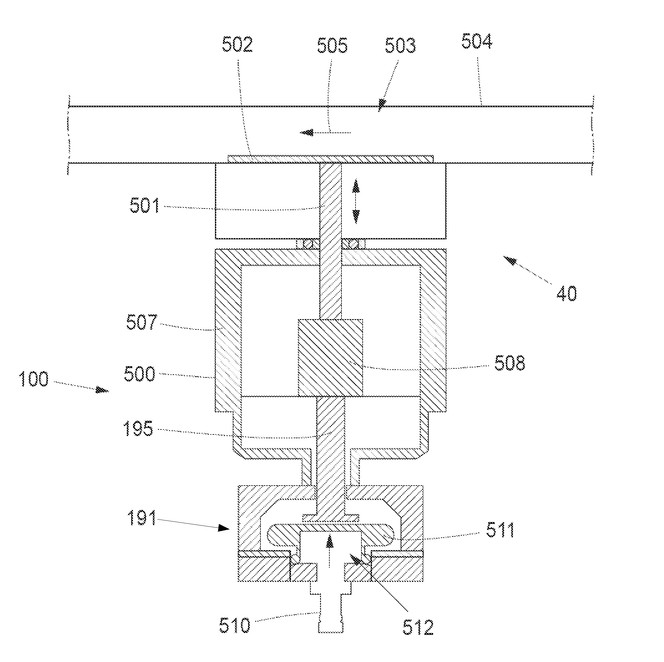
However, the valve has to be switched manually by means of a lever to the emergency mode and in this emergency mode the valve functions as a conventional mechanical, spring biased, pressure limiting valve with all the drawbacks thereof.

Method used


Image

  • Expiratory valve of an anesthetic breathing apparatus having safety backup
  • Expiratory valve of an anesthetic breathing apparatus having safety backup
  • Expiratory valve of an anesthetic breathing apparatus having safety backup

Examples


Embodiment Construction

[0032]Specific embodiments of the invention now will be described with reference to the accompanying drawings. This invention may, however, be embodied in many different forms and should not be construed as limited to the embodiments set forth herein; rather, these embodiments are provided so that this disclosure will be thorough and complete, and will fully convey the scope of the invention to those skilled in the art. The terminology used in the detailed description of the embodiments illustrated in the accompanying drawings is not intended to be limiting of the invention. In the drawings, like numbers refer to like elements.

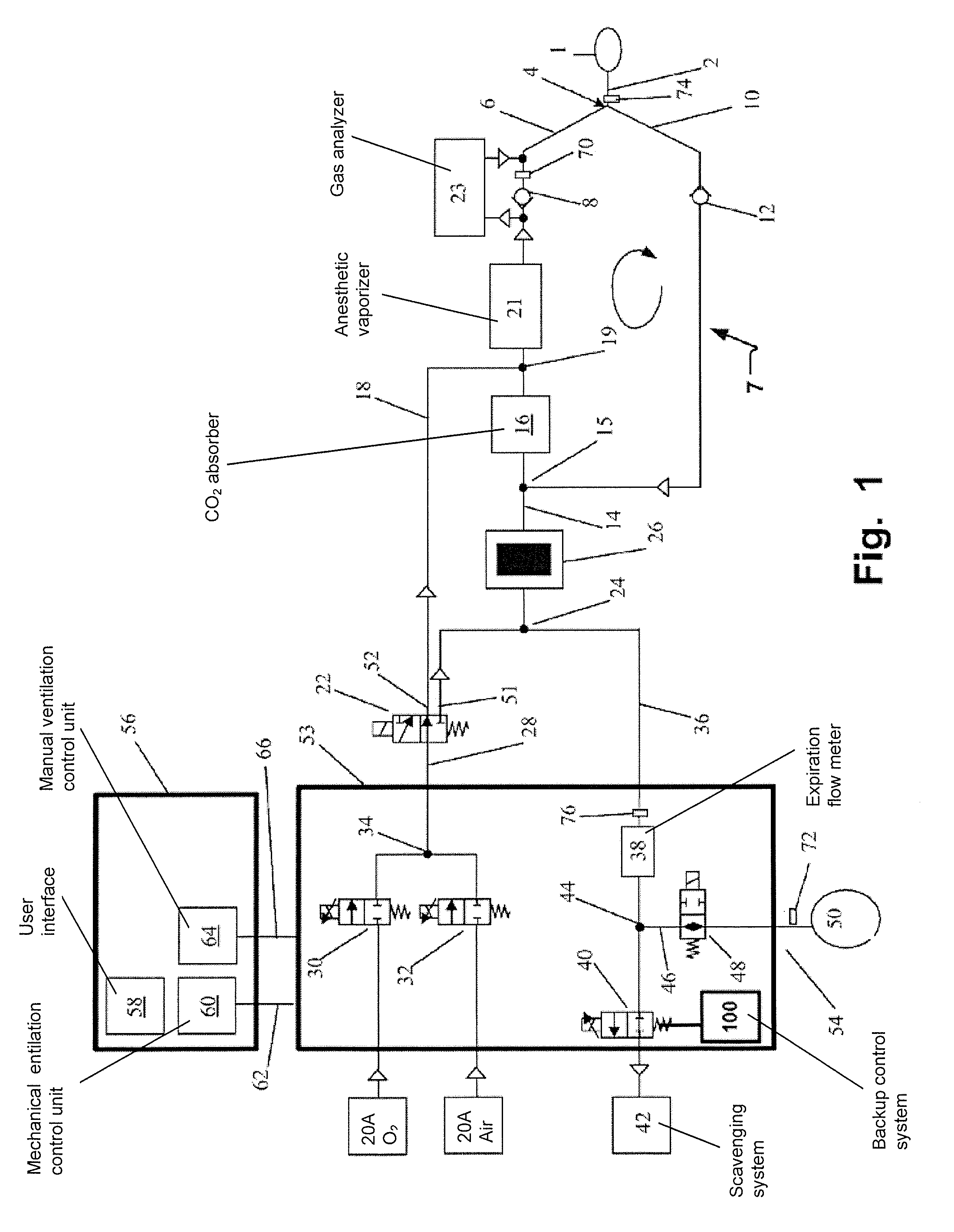
[0033]FIG. 1 shows schematically, a breathing circuit of an anesthetic breathing circuit, coupled to a circle system 7 with a mechanical ventilation system 53 and a manual ventilation system 54.

[0034]The airways of a patient 1 are connected to a patient tube 2 of a Y-piece 4 in a circular tubing system with an inspiration tube 6 provided with a one-way inspira...


PUM


Abstract

A ventilatory valve controls a pressure level in a patient breathing circuit of an anesthetic breathing apparatus. The ventilatory valve has a valve unit having a controllable restriction to control the pressure level in an expiratory branch of the breathing circuit of the anesthetic breathing apparatus, an electrical operating unit for the valve unit, configured to electrically control the restriction during electrical operation of the anesthetic breathing apparatus, and a non-electrical operating unit (100) for the valve unit, configured to non-electrically control the restriction upon electrical defective or powerless operation of the anesthetic breathing apparatus.

Description

BACKGROUND OF THE INVENTION[0001]1. Field of the Invention[0002]This invention pertains in general to the field of expiratory valves of an anesthesia patient breathing circuit in an anesthetic breathing apparatus. More particularly, the invention relates to an anesthetic breathing apparatus having an expiratory valve providing control of expiratory flow and pressure during a mechanical ventilation operation mode and providing a pressure-limiting function during manual ventilation operating mode of the anesthesia system.[0003]2. Description of the Prior Art[0004]Anesthesia patient breathing circuits of anesthetic breathing apparatuses, such as anesthesia machines, are utilized to convey gases containing an anesthetic vapor to a patient to carry out a narcosis of the patient. An anesthesia machine having a respiratory anesthesia delivery system comprising such an anesthesia patient breathing circuit provides a mixture of such gases and vaporized anesthetic agents. This mixture is conv...

Claims


Application Information

Patent Timeline
Patent Type & Authority Patents(United States)
IPC IPC(8): A62B9/02A61M16/20A61M16/00A61M16/01A61M16/10A61M16/22
CPCA61M16/104A61M16/01A61M16/20A61M16/0081A61M16/205A61M16/206A61M16/209A61M16/0075A61M16/0078A61M16/22A61M2016/0027A61M2205/16A61M16/208A61M16/0093A61M16/085A61M16/0866
Inventor DAHLSTROM, BOTORNESEL, CARL MAGNUSDANIELSEN, LARS
Owner MAQUET CRITICAL CARE
Learn More