Spark-ignited gas engine

Inactive Publication Date: 2009-07-02
HOERBIGER WIEN GMBH
View PDF11 Cites 4 Cited by
  • Summary
  • Abstract
  • Description
  • Claims
  • Application Information

AI Technical Summary

Benefits of technology

[0011]This object is achieved for the gas engine according to the invention in that a controlled valve is arranged in the fuel line upstream of the fuel feed valve so that in the fuel line between the fuel feed valve and the controlled valve a defined intermediate volume is created and gaseous fuel can be fed via the controlled valve into the intermediate volume. This object is achieved for the method according to the invention in that a controlled valve is arranged in the fuel line upstream of the fuel feed valve so that a defined intermediate volume is created in the fuel line between the fuel feed valve and controlled valve, and in that the amount of fuel fed into the cylinder is set by feeding a defined amount of fuel into the intermediate volume through the controlled valve. With the invention it is possible to admit a defined amount of gaseous fuel into each individual cylinder of the gas engine, thus allowing accurate, flexible control of

Problems solved by technology

This greatly stabilizes the response of the system as pressure control does not provide a linear and direct acting control of the injection event.
The increased open time results in a proportionate increase in the delivered fuel and in severe cases this can lead to engine flooding, stalling and backfire.
Furt

Method used


Image

  • Spark-ignited gas engine
  • Spark-ignited gas engine

Examples


Embodiment Construction

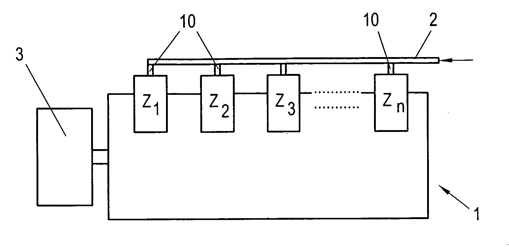
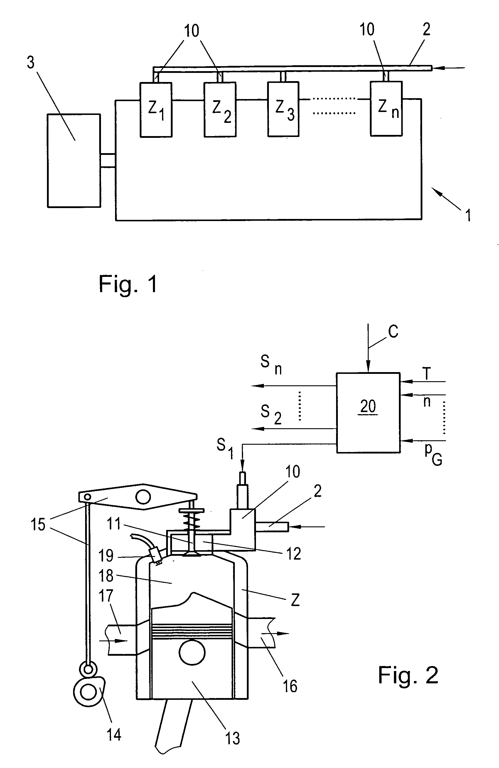
[0021]FIG. 1 shows a spark-ignited gas engine 1, e.g., a large-volume natural gas engine for the compression of natural gas during natural gas transport or of process gases in the chemical industry, which drives a load 3, e.g., a pump, a compressor, or a generator. The gas engine 1 has, in the known manner, a number of cylinders Z1 . . . Zn in which a respective piston 13 (see FIG. 2) is moved by the combustion of a gaseous fuel. Here, the gas mixture in the cylinder Z is ignited by a spark plug 19 at the end of the compression stroke. Each piston 13 is connected in the known manner by a connecting rod to a crankshaft, not shown here, via which the generated torque is transmitted to the load 3. Here, the gas engine 1 can be designed as a two or four-stroke engine. The fundamental design of such a spark-ignited gas engine is sufficiently known, and not discussed further here.

[0022]FIG. 2 shows by way of example a cylinder Z of the spark-ignited two-stroke gas engine 1. The cylinder Z...


PUM


Abstract

Conventional spark-ignited gas engines with a mechanically controlled fuel feed valve have several disadvantages in terms of operation, expensive control, irregular combustion or unstable and unreliable operation, which in turn can lead to operational and mechanical problems. In order to eliminate these disadvantages it is suggested, according to the invention, that a controlled valve is installed in the fuel line upstream of the fuel feed valve so that in the fuel line between fuel feed valve and controlled valve a defined intermediate volume is created and gaseous fuel is fed via the controlled valve into the intermediate volume.

Description

CROSS-REFERENCE TO RELATED APPLICATION[0001]This application is a continuation-in-part of application Ser. No. 11 / 892,418, filed Aug. 22, 2007, the priority of which is hereby claimed.BACKGROUND OF THE INVENTION[0002]1. Field Of The Invention[0003]The present invention relates to a spark-ignited gas engine with a number of cylinders, wherein on each cylinder a mechanical fuel feed valve for direct feeding of gaseous fuel into the cylinder and a fuel line opening into the cylinder are provided and the fuel line can be closed by the mechanical fuel feed valve in the direction of the cylinder. The invention also relates to a method for controlling such a gas engine and a method for converting a gas engine to such a gas engine.[0004]2. The Prior Art[0005]In spark-ignited gas engines, e.g., large-volume gas engines operated with natural gas in natural gas extraction and transport or in the chemical industry, the gaseous fuel (natural gas, liquefied gas, hydrogen, etc.) is metered at low ...

Claims


Application Information

Patent Timeline
IPC IPC(8): F01L9/04F01L1/34
CPCF02D41/0027F02D41/008Y02T10/32F02B2075/025F02M21/0251F02M21/0266F02D19/022F02D19/023F02M21/0239Y02T10/30
Inventor MATHEWS, HANSMCCOY, JR., JAMES J.STEINRUCK, PETER
Owner HOERBIGER WIEN GMBH
Why Eureka
Try Eureka