Centering slot for internal combustion engine

a technology of internal combustion engine and centering slot, which is applied in the direction of machine/engine, valve details, valve arrangement, etc., can solve the problems of failure to lock or inefficient locking,

Inactive Publication Date: 2015-03-10
HILITE GERMANY
View PDF48 Cites 10 Cited by
  • Summary
  • Abstract
  • Description
  • Claims
  • Application Information

AI Technical Summary

Benefits of technology

[0016]The invention also provides for a low part count and reduced complexity compared to many other mid-lock cam phaser systems.
[0018]The present invention provides for efficient locking when the engine is turned off, even when the pressure medium is cold, or when pressure medium pressure is reduced.
[0019]Still further, the present invention provides that the locking pin does not tend to become unlocked as a result of residual pressure being contained in the retard and / or advance chamber.

Problems solved by technology

Typical problems that occur in a cam phase locking system include, but are not limited to:failure to lock or inefficient locking when the pressure medium is cold;residual pressure in the retard and / or advance chamber (due to torque reversals of the camshaft (possibly caused by spring forces of the gas exchange valves)) tends to unlock the pin, especially when the engine-ignition is switched off but the crankshaft still rotates;failure to lock or inefficient locking when the engine is turned of andwhen pressure medium gets hot sometimes it leaks, causing the pump to deliver less pressure, which influences the cam phasers as well as the operation of the lock pin, wherein there may be a failure to lock or inefficient locking due to low pressure medium pressure.

Method used


Image

  • Centering slot for internal combustion engine
  • Centering slot for internal combustion engine
  • Centering slot for internal combustion engine

Examples


Embodiment Construction

[0032]While this invention may be susceptible to embodiment in different forms, there is shown in the drawings and will be described herein in detail, specific embodiments with the understanding that the present disclosure is to be considered an exemplification of the principles of the invention, and is not intended to limit the invention to that as illustrated.

[0033]An embodiment of the present invention provides a valve timing control device, in effect a cam phaser, for use with an internal combustion engine.

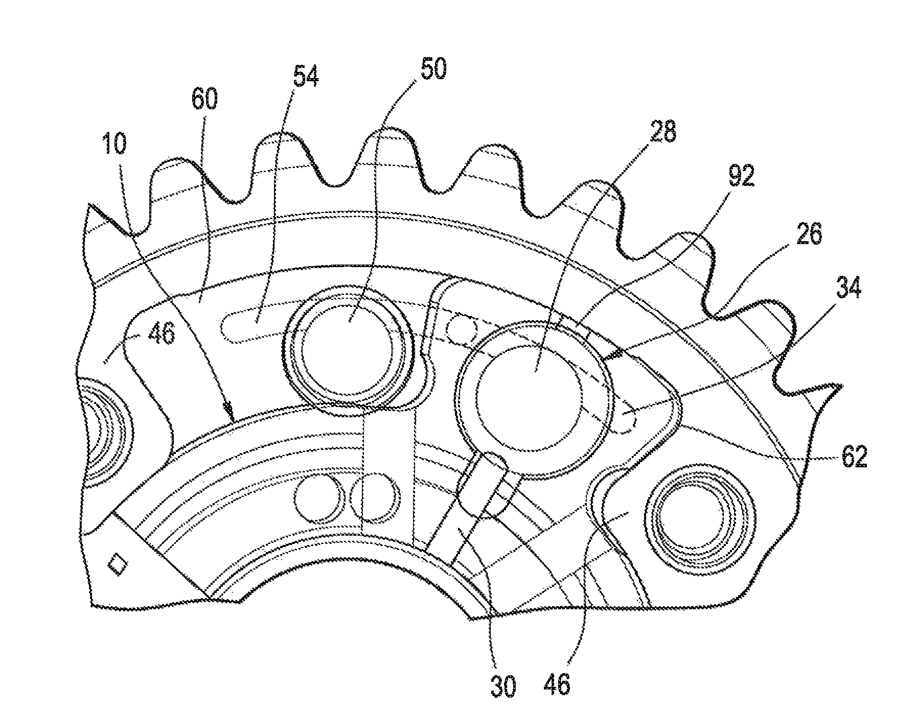
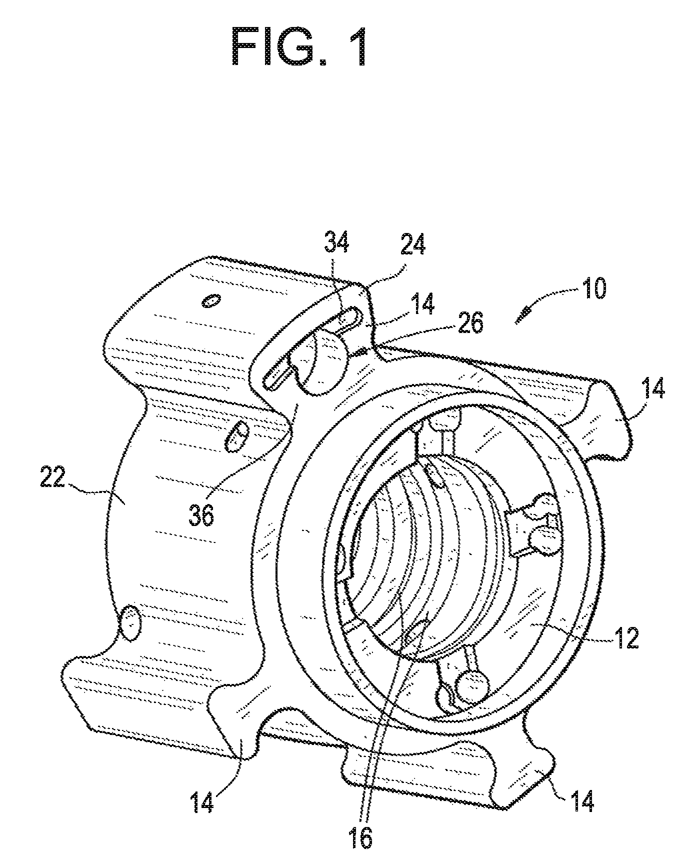
[0034]As shown in FIG. 1, one of the components of the valve timing control device comprises a rotor 10. The rotor 10 includes a hub 12, as well as vanes 14 which protrude radially away from the hub 12. The rotor 10 also includes annular channels 16 which communicate with additional channels 18, 20 (see FIG. 3) which lead to the outside surface 22 of the rotor 10. As will be described, these channels 16, 18, 20 provide fluid paths for pressure medium.

[0035]The rotor 10 also in...


PUM


Abstract

A valve timing control device for an internal combustion engine. The valve timing control device includes a rotor connected to a camshaft and having a plurality of vanes. A stator is engaged with the rotor, and includes a plurality of webs. Pressure chambers are provided between each of the webs and vanes. A centering slot is provided on the stator and / or the rotor. A pressure medium control valve is disposed in one of the vanes of the rotor, and is configured to not only selectively lock and unlock the position of the rotor relative to the stator, but is also configured such that pressure medium in the pressure chambers is veritable through the centering slot and thereafter through the pressure medium control valve.

Description

BACKGROUND OF THE INVENTION[0001]The present invention relates to a cam phaser of an internal combustion engine, wherein a centering slot is provided which tends to, at certain times depending on the stage of operation of the internal combustion engine, center and lock the rotor relative to the stator.[0002]A typical internal combustion engine provides that a crankshaft drives a drive wheel using a chain or drive belt. A stator is joined in a torsionally rigid manner to the drive wheel. As such, the stator is drive-connected to the crankshaft by means of this drive element and drive wheel.[0003]A corresponding rotor is engaged with the stator, and is joined to the camshaft in a torsionally rigid manner. The camshaft has cam lobes thereon which push against gas exchange valves in order to open them. By rotating the camshaft, the opening and closing time points of the gas exchange valves are shifted so that the internal combustion engine offers its optimal performance at the speed inv...

Claims


Application Information

Patent Timeline
Patent Type & Authority Patents(United States)
IPC IPC(8): F01L1/34
CPCF01L1/3442F01L2001/34456F01L2001/34469F01L2001/34426F01L2001/34463F01L2250/02F01L2250/04F01L1/34
Inventor MOREHEAD, JAMES ANTHONYGERSZEWSKI, WESSNYDER, JOHNCOLE, JOE S.HUTCHESON, JACK DOYLENANCE, STEVE
Owner HILITE GERMANY
Why Eureka
Try Eureka