Coupling element segments for a rotor of a turbomachine

a technology of turbomachine and coupling element, which is applied in the direction of liquid fuel engines, vessel construction, marine propulsion, etc., can solve the problems of reducing or eliminating the desired coupling between adjacent couplings, and the vibration behavior of the turbomachine rotor eventually deteriorates, so as to achieve convenient mounting

Inactive Publication Date: 2015-03-10
MAN ENERGY SOLUTIONS SA
View PDF19 Cites 0 Cited by
  • Summary
  • Abstract
  • Description
  • Claims
  • Application Information

AI Technical Summary

Benefits of technology

[0009]An object of one embodiment of the present invention is to provide a rotor of a turbomachine in which coupling of the coupling element segments of the rotor blades is ensured during operation and the rotor is easily mounted.
[0011]With the inventive rotor of a turbomachine, an optimal support and, therefore, an optimal coupling of the coupling element segments forming the coupling element or every coupling element is ensured by the contour of the coupling element segments of the rotor blades and the rotor is easily mounted. In this way, stress peaks in the coupling element of the rotor, or in every coupling element of the rotor, can be appreciably reduced in operation and the rotor can be mounted easily. Further, the resonant frequency behavior and, therefore, the vibration behavior of the rotor according to the invention are improved and the rotor can be mounted easily.

Problems solved by technology

This reduces or eliminates a desired coupling between adjacent coupling element segments so that the vibration behavior of the turbomachine rotor eventually deteriorates.

Method used


Image

  • Coupling element segments for a rotor of a turbomachine
  • Coupling element segments for a rotor of a turbomachine
  • Coupling element segments for a rotor of a turbomachine

Examples


Embodiment Construction

[0019]The present invention is directed to a rotor of a turbomachine, particularly a rotor of a compressor or of a turbine of a turbomachine constructed as a gas turbine or steam turbine. However, the invention is not limited to these applications; rather, the invention can be put to use in all turbomachine rotors.

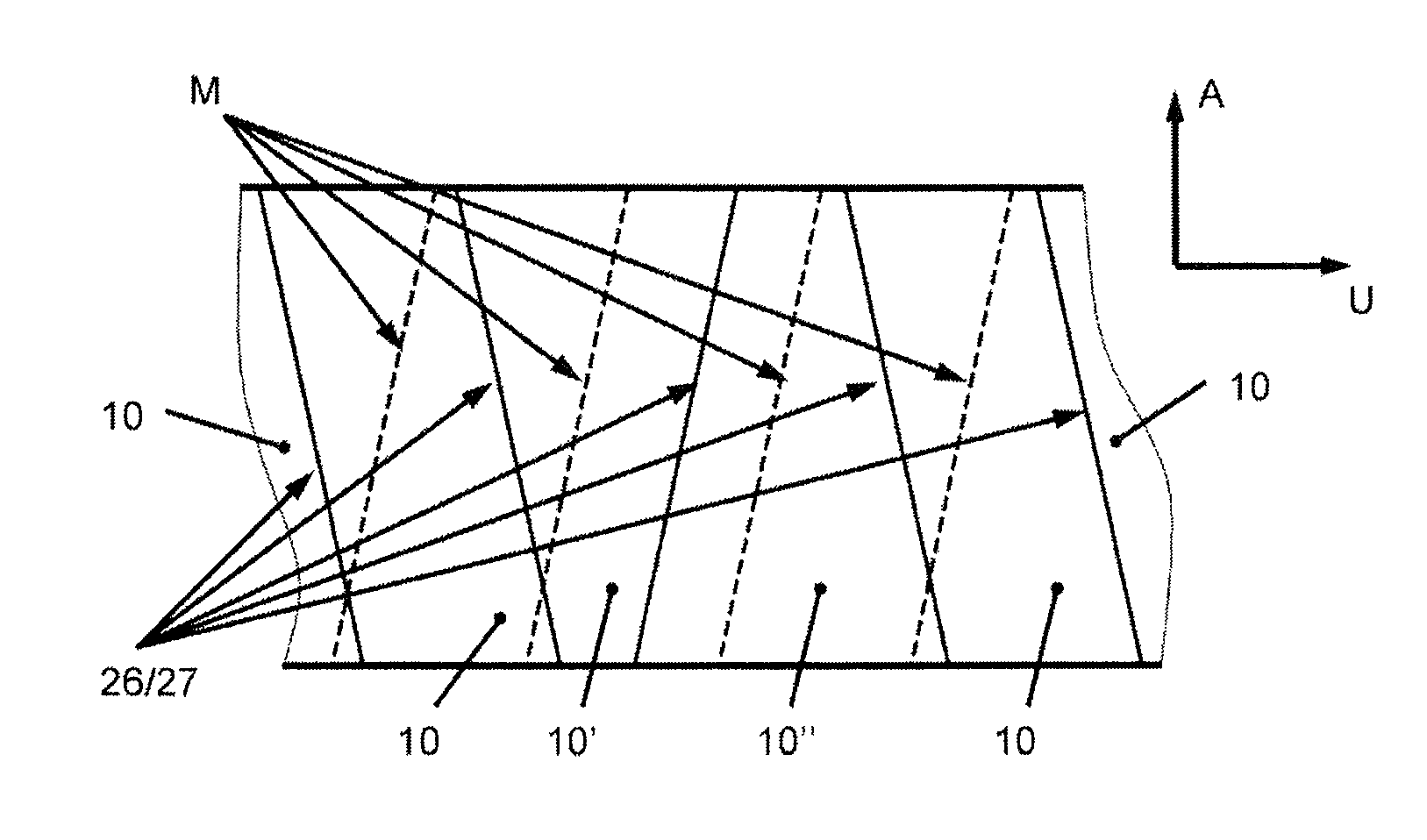
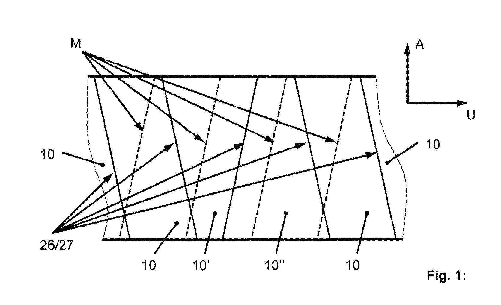
[0020]A rotor of a turbomachine basically has a rotor base body and a plurality of rotor blades fastened by blade roots to the rotor base body. The rotor base body and the blade roots of rotor blades are not shown in detail in FIGS. 1 to 5 because those skilled in the art will be familiar with these details. However, it should be noted in this connection that every rotor blade is fastened by its blade root to the rotor base body in a slot of the rotor base body in a mounting direction defined by the blade roots. For this purpose, a separate slot can be provided at the rotor base body for every rotor blade or blade root of every rotor blade. Further, it is possible for all ...


PUM


Abstract

A rotor of a turbomachine has a rotor base body and a plurality of rotor blades. Every rotor blade has a blade body and a coupling element segment. The coupling element segment of every rotor blade is contoured at a first side and at a second side opposite the first side that, at the first side and at the second side, a radially outer edge of the respective coupling element segment extends substantially in axial direction and a radially inner edge of the respective coupling element segment extends substantially in axial direction respectively delimit two surfaces separated from one another by a separating line. In at least one circumferential position of the rotor between two directly adjacent rotor blades, the separating lines run approximately parallel to, or in alignment with, the mounting direction of the rotor blades at the rotor base body, which mounting direction is defined by the blade roots. In every other circumferential position between two directly adjacent rotor blades, the separating lines formed at directly adjacent sides of the coupling element segments are oblique relative to the mounting direction.

Description

BACKGROUND OF THE INVENTION[0001]1. Field of the Invention[0002]The invention is directed to a rotor of a turbomachine.[0003]2. Description of the Related Art[0004]A rotor of a turbomachine, particularly of a gas turbine or steam turbine, has a rotor base body and a plurality of rotor blades that are fastened to the rotor base body. The rotor blades of the turbomachine rotor have a blade root and a blade body. Every rotor blade is fastened by its blade root to the rotor base body in a slot of the rotor base body in a mounting direction defined by the blade roots, and every rotor blade has in the region of its blade body at least one coupling element segment constructed as an outer shroud segment when this coupling element segment is positioned on the radially outer side of the blade body. The coupling element segments, particularly the outer shroud segments, of all of the rotor blades of a turbomachine rotor of this kind together form at least one circumferentially closed coupling e...

Claims


Application Information

Patent Timeline
Patent Type & Authority Patents(United States)
IPC IPC(8): F01D5/22
CPCF01D5/225F05D2250/73
Inventor RAIBLE, TILMANN
Owner MAN ENERGY SOLUTIONS SA
Why Eureka
Try Eureka