LED control apparatus

a technology of led control and control apparatus, which is applied in the direction of electric variable regulation, process and machine control, instruments, etc., can solve the problems of high cost of artificial light fixtures, and the type of lighting fixtures cannot meet the needs of common users, so as to achieve effective control of current ratio

Active Publication Date: 2015-03-10
JUST POWER INTEGRATED TECH
View PDF6 Cites 12 Cited by
  • Summary
  • Abstract
  • Description
  • Claims
  • Application Information

AI Technical Summary

Benefits of technology

[0005]A primary objective of the present invention is to provide an LED control apparatus that utilizes a microcontroller unit (MCU) electrically connected to an LED driver on one end thereof to control an LED light source at an output end thereof in order to effectively control the current ratio guided into each one of the LED light modules and such that the color temperature of the light shone therefrom can be changed accordingly.
[0006]To achieve the aforementioned objective, the present invention provides an LED control apparatus for controlling a color temperature of at least one LED light module, and the LED control apparatus comprises an LED driver electrically connected to the at least one LED light module; a power conversion module; and a microcontroller unit electrically connected to the power conversion module to control a current output ratio of the LED driver; wherein the microcontroller unit comprises a first control point electrically connected to the LED driver and at least one second control point and at least one third control point electrically connected to the at least one LED module; and wherein the at least one second control point and the at least one third control point are electrically connected to at least one current controller for controlling a current therethrough. Accordingly, as the LED control apparatus of the present invention is electrically connected to the LED light modules, the municipal electricity on grid transmits power to the power conversion module and the LED driver for activation thereof, which is too being controlled by the microcontroller unit to adjust the current flow ratio guided therein in order to provide the necessary current specifically required by the LED lighting fixtures under different settings. By using the microcontroller unit and by electrically connecting one end of the microcontroller unit to the LED driver having the LED light modules electrically connected to the output end thereof, the luminance of the LED light modules can be controlled individually at the output ends thereof and the color temperature of the light of such LED fixtures at work can be changed such that the technical effects of providing illumination lighting with different color temperatures according to the needs of different applications and settings can be advantageously achieved.

Problems solved by technology

However, under normal practices, different light sources with different color temperatures must be provided and installed onto a lighting fixture in order to achieve the color temperature changes from the light fixture; and in most cases, different light sources of unequal color temperatures must be controlled separately by at least two distinct lighting circuits, which tends to cause the problem to common households as such new and unfitted lighting circuits need to be incorporated into the existing ones with the current lighting fixtures; therefore, the costs of such artificial light fixtures are likely to increase significantly.
In other words, such type of lighting fixtures cannot satisfy the needs of common users that demand lights to have different color temperatures and to be set according to various conditions and environment desired.

Method used


Image

  • LED control apparatus
  • LED control apparatus
  • LED control apparatus

Examples


Embodiment Construction

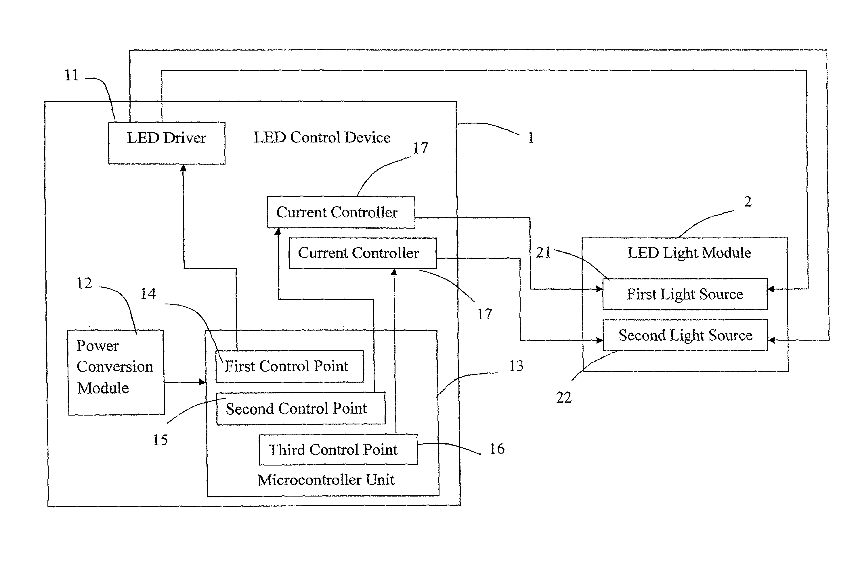
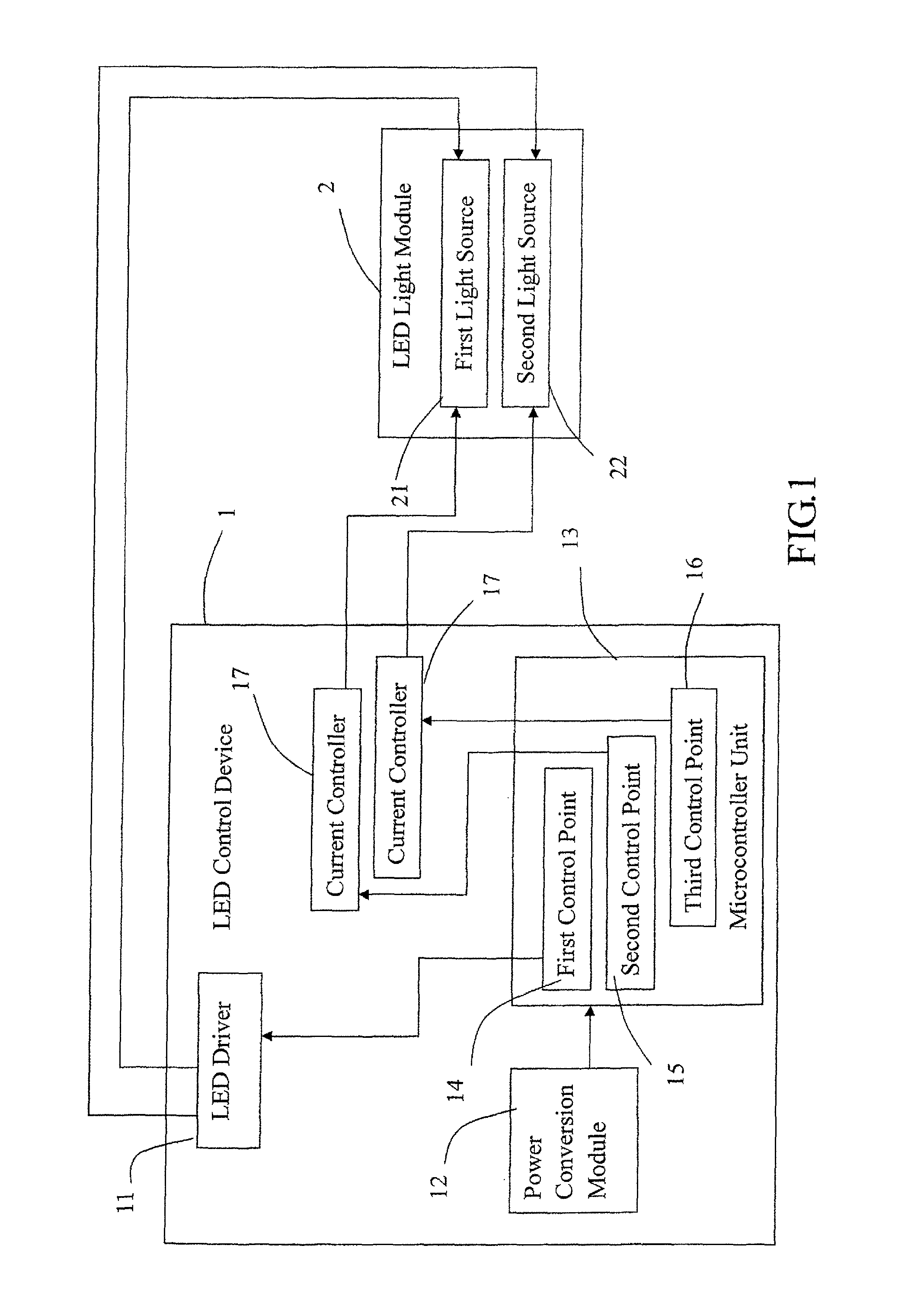
[0011]Please refer to FIG. 1 showing a preferred embodiment of an LED control apparatus of the present invention. As shown in the figure, the LED control apparatus of the present invention for controlling a color temperature change of at least one LED light module 2, wherein the LED control apparatus 1 comprises:

[0012]an LED driver 11 electrically connected to the at least one LED light module 2;

[0013]a power conversion module 12; and

[0014]a microcontroller unit 13 electrically connected to the power conversion module 12 to control a current output ratio of the LED driver 11; wherein the microcontroller unit 13 comprises a first control point 14 electrically connected to the LED driver 11 and at least one second control point 15 and at least one third control point 16 electrically connected to the at least one LED module 2; and at least one current controller 17 for controlling a current therethrough is electrically connected between the at least one second control point 15 with the...


PUM


Abstract

Provided is an LED control apparatus for controlling a color temperature of at least one LED light module, and the LED control apparatus includes an LED driver electrically connected to the LED light modules; a power conversion module; and a microcontroller unit electrically connected to the power conversion module to control a current output ratio of the LED driver; the microcontroller unit comprises a first control point connected to the LED driver and second and third control points connected to the LED modules; wherein the second and third control points are electrically connected to current controllers for controlling a current therethrough. By using the microcontroller connected to the LED driver to control the current outputs to the LED light modules, the current ratio of the LED light modules can be effectively controlled in order to change the color temperatures of the LED light modules.

Description

TECHNICAL FIELD OF THE INVENTION[0001]The present invention is related to an LED control apparatus, more particularly, to an LED control apparatus utilizing an LED driver capable of controlling the amount of the current output ratio at an output end thereof in order to achieve the color temperature changes of illuminated LED light modules connected thereto.DESCRIPTION OF THE PRIOR ART[0002]As lighting fixtures and lights play a significant role in our daily lives, it is found that according to various conditions including the time, place and environment, different degrees of luminance and color temperatures of the lighting fixtures are required to obtain optimal lighting effects and feels. In other words, a light source illuminated at a certain color temperature is able to achieve a particular atmosphere while providing a completely different person feeling to the surrounding of the light, which may include soothing and comforting feelings of a person under a certain color temperatu...

Claims


Application Information

Patent Timeline
Patent Type & Authority Patents(United States)
IPC IPC(8): H05B33/08H05B44/00
CPCH05B33/0857H05B45/20
Inventor YANG, CHING-NANKUO, CHIN-HUI
Owner JUST POWER INTEGRATED TECH
Why Eureka
Try Eureka