

Imaging lens
a technology of imaging and lens, applied in the field of imaging lenses, can solve the problems of not being able to meet the demand for wider angles of view, not being able 3.2 being considered to provide sufficient brightness, etc., to meet the needs of compactness and thinness, wide angle of view, and low cost.
- Summary
- Abstract
- Description
- Claims
- Application Information
AI Technical Summary
Benefits of technology
Problems solved by technology
Method used
Image


Examples
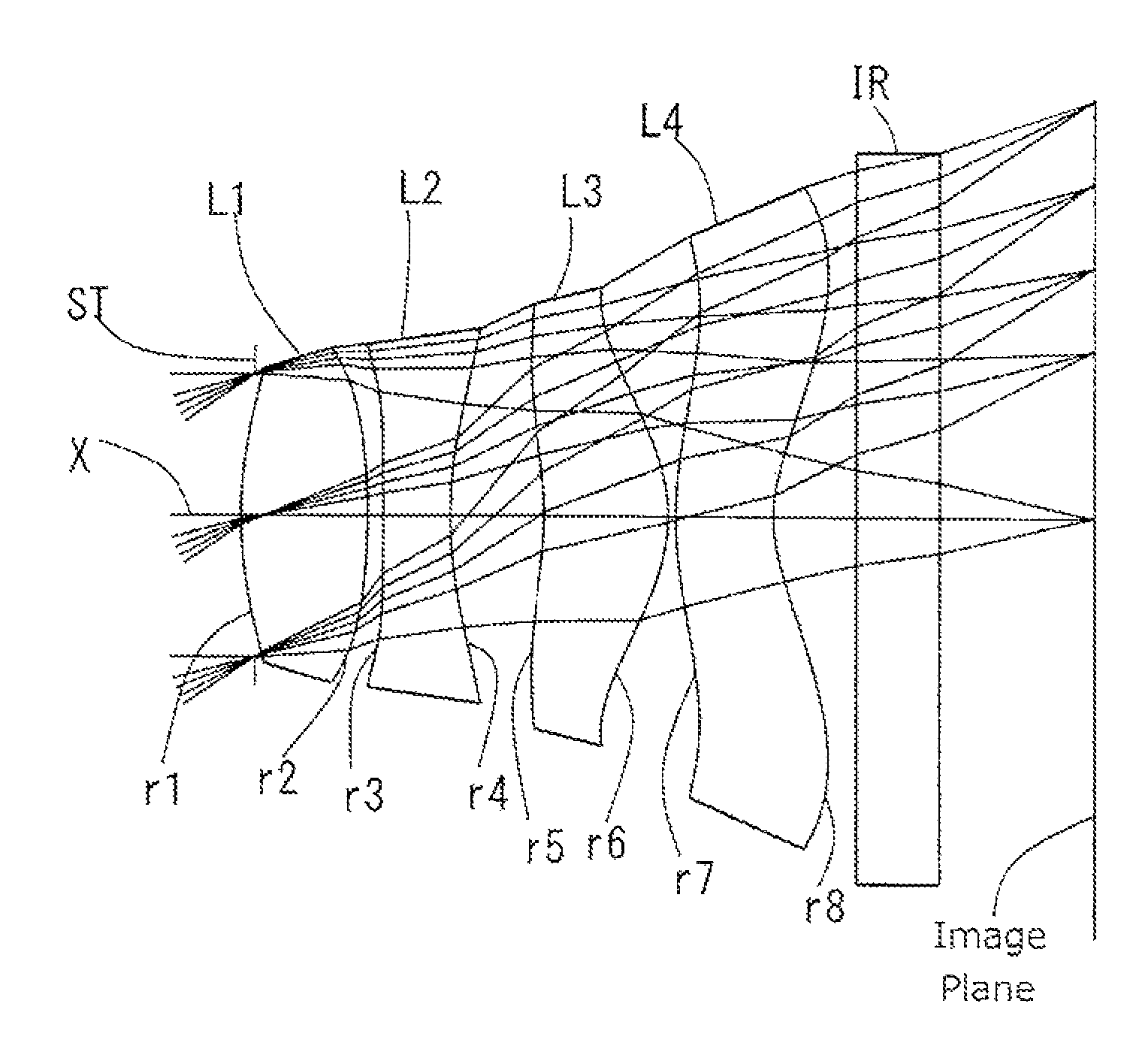
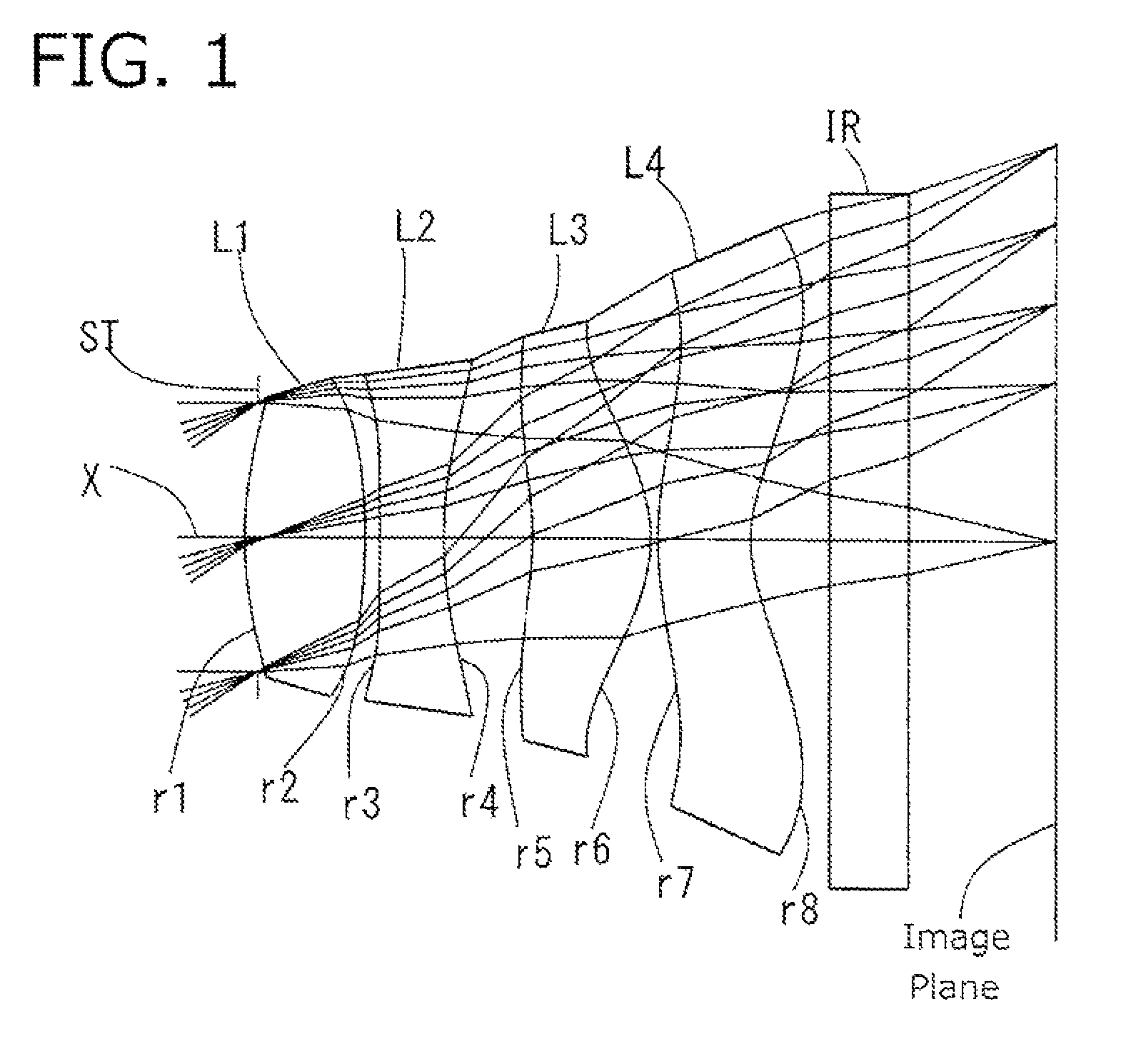
embodiment 1
[0110]The basic lens data of Embodiment 1 is shown below in Table 1.
[0111]
TABLE 1Numerical Example 1in mmf = 2.22Fno = 2.20ω(deg) = 33.7ih = 1.50TTL = 2.97EPD = 1.01Surface DataRefractiveCurvatureSurfaceIndexAbbe NumberSurface No. iRadius rDistance dNdνd(Object Surface)InfinityInfinityStopInfinity−0.051*1.4940.4601.534656.162*−1.8000.0563*−6.8350.2451.635523.914*1.8440.3445*−1.1740.4521.534656.166*−0.5460.0277*1.2980.3551.534656.168*0.5250.2509 Infinity0.31.516864.2010 Infinity0.603Image PlaneInfinityConstituent Lens DataLensStart SurfaceFocal Length111.60523−2.260351.52847−1.960Composite Focal Lengthf123.627f344.182Aspheric Surface Data1st Surface2nd Surface3rd Surface4th Surfacek2.915E+00−4.679E+010.000E+00−2.181E+01A4−1.722E−012.681E−021.110E+001.173E+00A6−2.179E−01−3.856E+00−9.832E+00−6.008E+00A8−7.109E−018.818E+002.256E+011.300E+01A10−3.264E+00−7.419E+00−1.399E+01−1.325E+01A121.270E+000.000E+00−3.179E+005.704E+00A140.000E+000.000E+000.000E+000.000E+00A160.000E+000.000E+000.000E...
embodiment 2
[0114]The basic lens data of Embodiment 2 is shown below in Table 2.
[0115]
TABLE 2Numerical Example 2in mmf = 2.21Fno = 2.19ω(deg) = 33.9ih = 1.50TTL = 2.97EPD = 1.01Surface DataRefractiveCurvatureSurfaceIndexAbbe NumberSurface No. iRadius rDistance dNdνd(Object Surface)InfinityInfinityStopInfinity−0.051*1.4830.4901.534656.162*−1.8000.0903*−2.4710.2451.635523.914*5.0000.2715*−1.0540.4601.534656.166*−0.5730.0277*1.2030.3631.534656.168*0.5330.2509 Infinity0.31.516864.2010 Infinity0.594Image PlaneInfinityConstituent Lens DataLensStart SurfaceFocal Length111.60523−2.570351.76247−2.206Composite Focal Lengthf123.199f345.345Aspheric Surface Data1st Surface2nd Surface3rd Surface4th Surfacek0.000E+000.000E+000.000E+000.000E+00A4−5.632E−026.521E−011.297E+001.217E+00A6−2.367E−01−4.266E+00−8.803E+00−6.169E+00A8−3.804E−029.279E+002.153E+011.287E+01A10−1.922E+00−7.375E+00−1.696E+01−1.302E+01A122.162E+000.000E+00−2.775E−016.020E+00A140.000E+000.000E+000.000E+000.000E+00A160.000E+000.000E+000.000E+0...
embodiment 3
[0118]The basic lens data of Embodiment 3 is shown below in Table 3.
[0119]
TABLE 3Numerical Example 3in mmf = 2.22Fno = 2.20ω(deg) = 33.9ih = 1.50TTL = 2.98EPD = 1.01Surface DataRefractiveCurvatureSurfaceIndexAbbe NumberSurface No. iRadius rDistance dNdνd(Object Surface)InfinityInfinityStopInfinity−0.0571*1.4590.4711.534656.162*−1.8490.0573*−7.0750.2451.635523.914*2.2470.2725*−1.2180.5471.534656.166*−0.5500.0277*2.1050.3741.534656.168*0.6000.2509 Infinity0.31.516864.2010 Infinity0.557Image PlaneInfinityConstituent Lens DataLensStart SurfaceFocal Length111.60523−2.657351.45947−1.718Composite Focal Lengthf123.042f345.824Aspheric Surface Data1st Surface2nd Surface3rd Surface4th Surfacek0.000E+000.000E+000.000E+000.000E+00A4−7.682E−026.039E−017.730E−015.671E−01A6−3.605E−02−5.741E+00−7.379E+00−3.803E+00A8−2.638E+001.340E+011.496E+018.367E+00A108.511E+00−1.344E+01−7.892E+00−1.203E+01A12−2.045E+010.000E+00−4.153E−018.802E+00A140.000E+000.000E+000.000E+000.000E+00A160.000E+000.000E+000.000E+...
PUM
 Abstract
Description
Claims
Application Information