Protective headgear

a protective head and helmet technology, applied in the field of protective headgear, can solve the problems of heavy helmets, people who tend not to wear, people with a tendency to catch heat, etc., and achieve the effects of deep impact protection, absorbing sweat, and adding impact protection

a protective head and helmet technology, applied in the field of protective headgear, can solve the problems of heavy helmets, people who tend not to wear, people with a tendency to catch heat, etc., and achieve the effects of deep impact protection, absorbing sweat, and adding impact protection

US8978167B2Inactive Publication Date: 2015-03-17BLAIR MARY LYNNE

Image

  • Protective headgear
  • Protective headgear
  • Protective headgear

Examples


Embodiment Construction

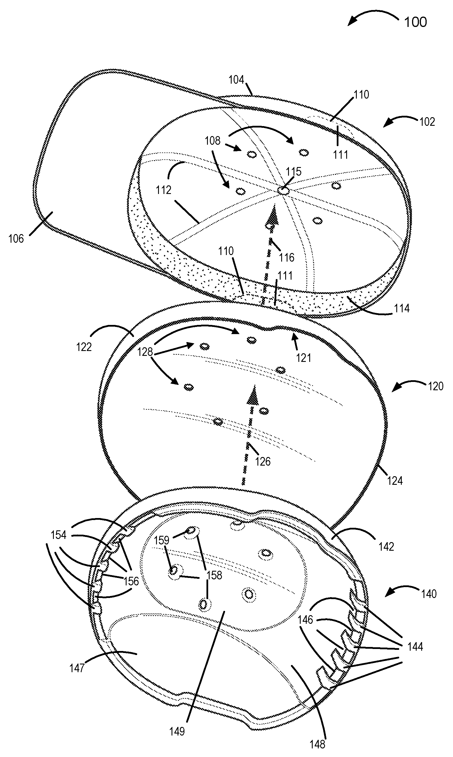
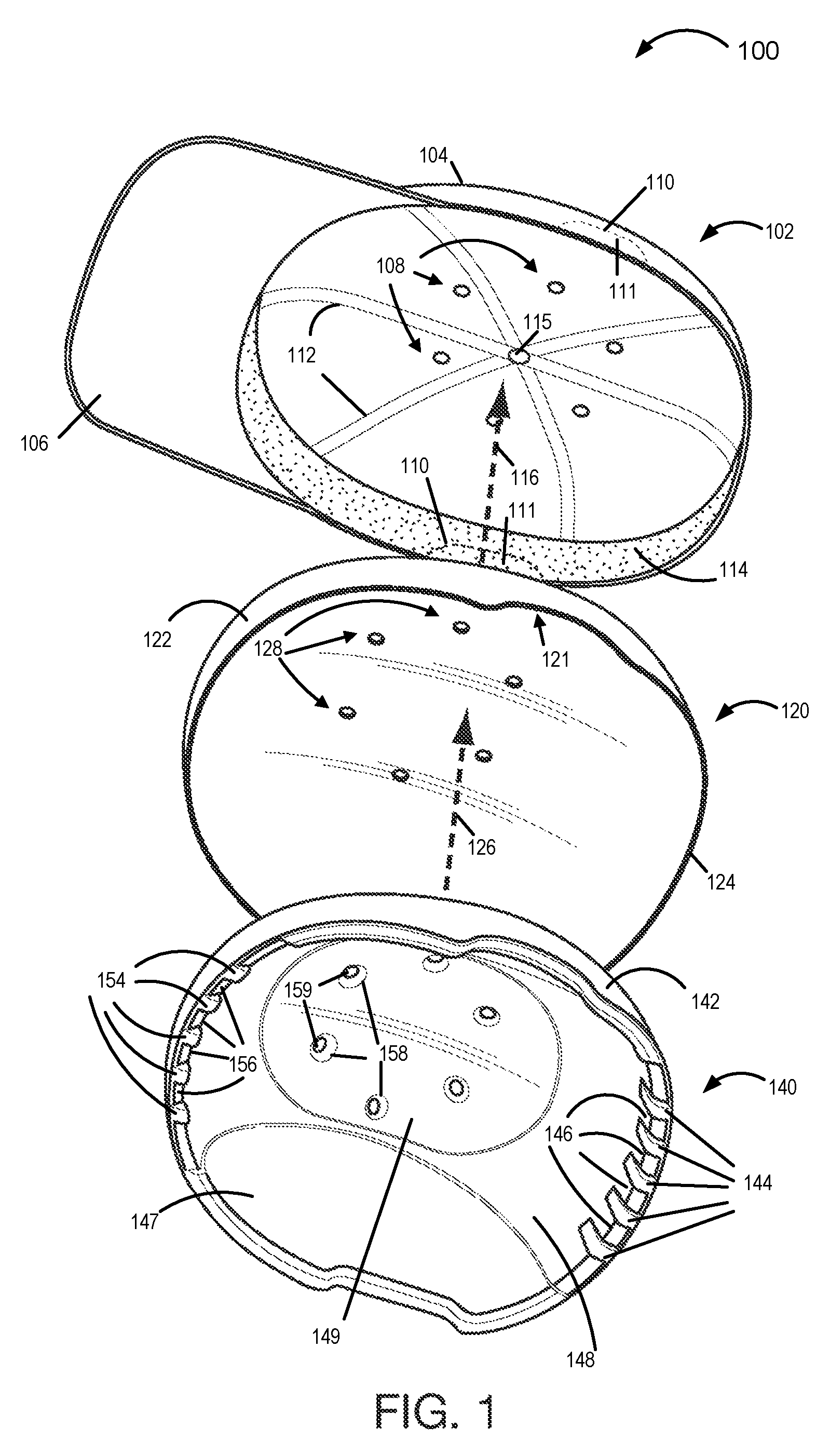
[0062]Referring to the drawings, FIG. 1 illustrates an exemplary protective device 100 in the form of headgear comprising a cap 102, an outer shell 120, and a corresponding inner foam liner 140. As illustrated by arrow 126, the foam liner is inserted into the hard outer shell 120. The foam liner 140 is normally secured to the hard outer shell via an adhesive or by molding the foam liner directly into the shell so that it is adheres and conforms to the inside surface of the hard outer shell. While shown as separate components, during use the foam inner liner is secured to the hard outer shell and remains attached thereto as a combined outer shell and foam liner assembly, referred to herein as the combined assembly 120, 140. The combined assembly can be inserted into the cap 102 when protection from impacts is desired as shown by arrow 116. Depending on the embodiment the thickness of the foam liner may vary. In some embodiments the thickness of the foam liner is between 4 mm and 32 m...


PUM


Abstract

A protective headgear device including a fabric cap (102) into which a hard shell (120) of reinforced fibers is inserted. A foam liner 140 or foam inserts (1500) are secured to the hard outer shell 120 and serve a shock absorbing function. The foam liner (14) and / or foam inserts (120) include or form grooves and / or channels used to direct hot air towards the top center of the headgear assembly where the hot air can be vented through holes which extend through the cap (102) and hard outer shell (120). The holes may pass through the foam liner 140 or meet up with holes on channels in or between the foam inserts through which air can pass. The hard outer shell maybe thinnest on top and thicker on the left and right sides. The center front and rear may be the same thickness as the top of the hard shell.

Description

RELATED APPLICATIONS[0001]The present application is related to Australian provisional patent application 2010902662, filed Jun. 18, 2010 which is hereby expressly incorporated by reference in its entirety.FIELD OF THE INVENTION[0002]The invention relates to protective headgear and, more particularly, protective headgear suitable for use as or with caps that may be worn at sporting or events.BACKGROUND OF THE INVENTION[0003]As the medical understanding of the potential long lasting and sometimes permanent effects of head trauma can have on affected individuals has increased, there has been an appreciation of the fact that protective headgear can reduce such trauma significantly in many cases.[0004]Various potential applications for protective headgear include baseball games, golf matches and / or other sporting events where participants and / or fans may be hit with a ball or other flying object. In addition to ball impacts, a person may fall or collide with another person or object whi...

Claims


Application Information

Patent Timeline
17 Mar 2015
Publication
US8978167B2
IPC
A42B3/00; A42B1/08; A42B3/12
CPC
A42B3/128; A42B1/08; A42B3/125; A42B3/28
Inventors
BLAIR, MARY LYNNE