Pneumatic tire/rim assembly

a pneumatic tire and assembly technology, applied in the field of pneumatic tires/rim assemblies, can solve the problems of increasing tire mass, reducing run-flat durability, and unable to meet the demand for lower fuel consumption, so as to improve run-flat durability, reduce tire mass, and increase the durability of run-flat running.

Inactive Publication Date: 2015-03-17
THE YOKOHAMA RUBBER CO LTD
View PDF13 Cites 1 Cited by
  • Summary
  • Abstract
  • Description
  • Claims
  • Application Information

AI Technical Summary

Benefits of technology

[0015]In the present invention, at least part of the air bladder is formed of the sealing layer made of the thermoplastic resin or the thermoplastic elastomer composition obtained by blending an elastomer in the thermoplastic resin. For this reason, the internal pressure of the air bladder is maintained by the air impermeability of this sealing layer, which extends continuously throughout the air bladder at a specified level, in order to maintain such internal pressure. This makes it possible to enhance the durability for run-flat running. In addition, because no special reinforcement layer such as a reinforcement cord layer or a rigid plate is needed to be arranged on the air bladder, the mass of the assembly does not increase. Furthermore, because at least part of the rubber material of the air bladder is replaced with the sealing layer, whose mass is smaller than the mass of the rubber, the mass of the tire can be reduced.
[0016]In addition, the sealing layer is made of the thermoplastic resin or the thermoplastic elastomer composition whose tan δ is smaller than that of the rubber thereby producing heat less than the rubber. Thus, it is possible to inhibit heat from being produced due to repeated deformation of the air bladder during run-flat running. For this reason, the run-flat durability can be enhanced efficiently.

Problems solved by technology

However, both proposals have a problem that the arrangement of the reinforcement cord layer or the rigid plate increases the mass of the tire, and a demand for lower fuel consumption cannot be accordingly satisfied.
In addition, there is a problem that it is difficult to maintain the internal pressure of the air bladder for a long period of time, and decrease in the internal pressure of the air bladder accordingly results in decrease in the run-flat durability.

Method used


Image

  • Pneumatic tire/rim assembly
  • Pneumatic tire/rim assembly

Examples


examples

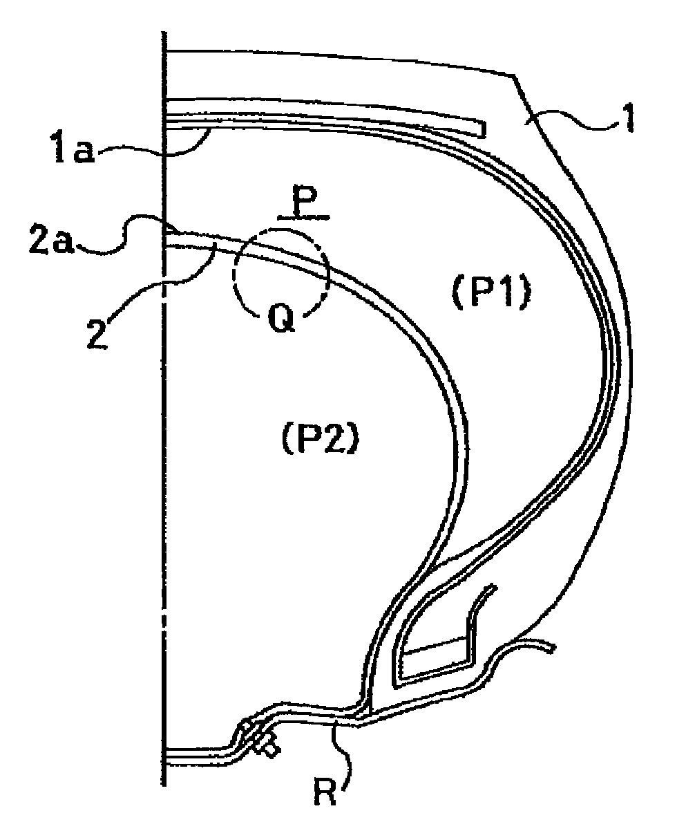
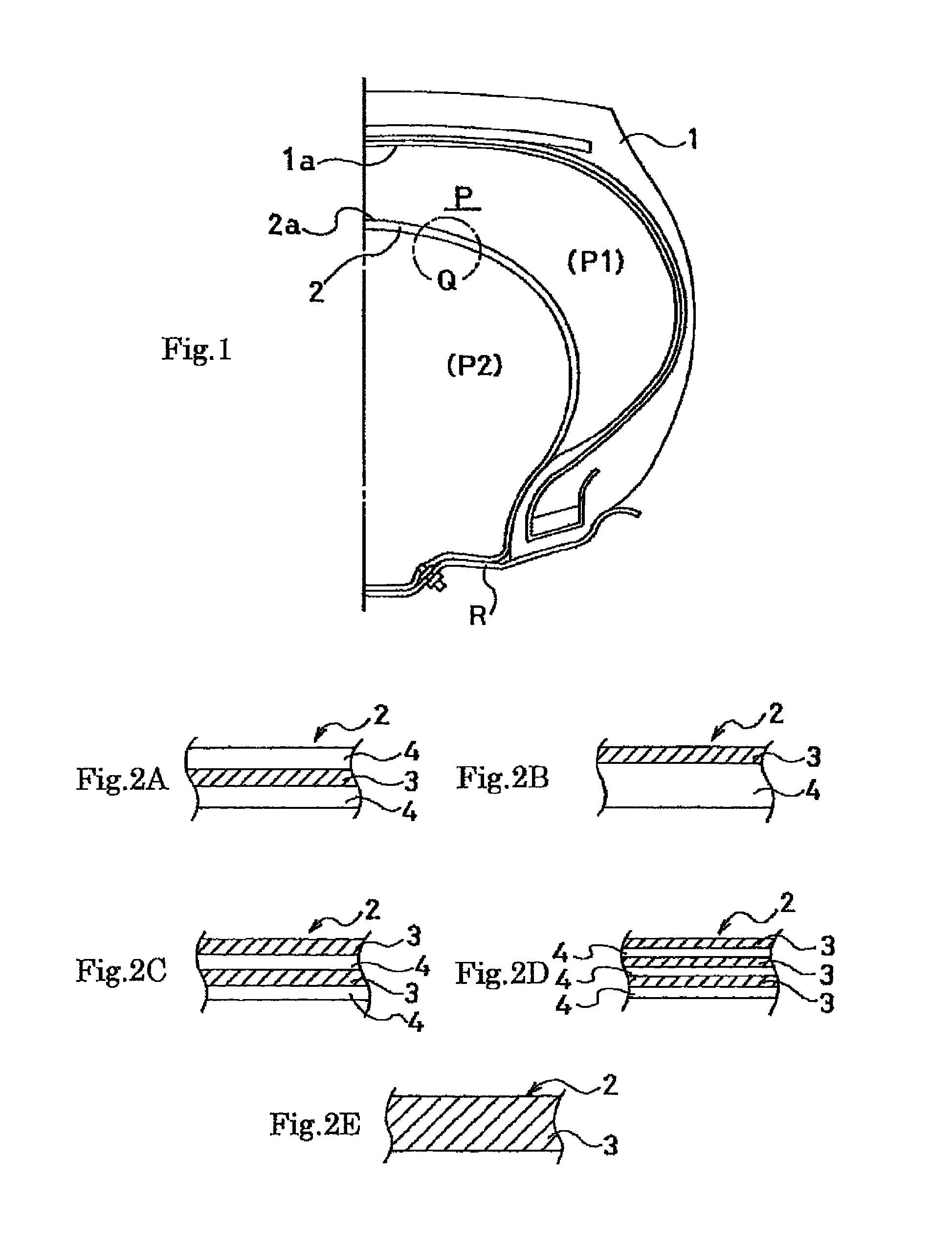
[0044]A conventional type of assembly (Conventional Example) and assemblies according to the present invention (Examples 1 to 8) were produced with a tire size of 295 / 75 R22.5, and with the tire structure shown in FIG. 1, the assemblies differing from one another in arrangement of the sealing layer(s) in the air bladder, a ratio of the volume of the sealing layer(s) to the volume of the air bladder (simply referred to as a “ratio of sealing layer(s)” in Table 1), and presence or absence of the sealing layer arranged on the tread inner circumferential surface as shown in Table 1. Note that for each assembly, the thickness of the air bladder was set at 1.2 mm, and a butyl-based rubber composition was used as the material for the rubber layer. A blend of a nylon 6 / 66 copolymer and a brominated isobutylene para-methylstyrene copolymer (Br-IPMS) was commonly used as the material for the sealing layers of the assemblies according to the present invention.

[0045]For each assembly, the mass ...


PUM

PropertyMeasurementUnit
frequencyaaaaaaaaaa
temperatureaaaaaaaaaa
thicknessaaaaaaaaaa

Abstract

Provided is a pneumatic tire / rim assembly which is improved in the run-flat durability with the mass of the tire being reduced. In a pneumatic tire / rim assembly with a run-flat capability, an air bladder (2) made of a circular ring-shaped film body is inserted inside a pneumatic tire (1) mounted on a rim (R). At least part of the film body is formed of a sealing layer (3) made of a thermoplastic resin or a thermoplastic elastomer composition obtained by blending an elastomer in a thermoplastic resin.

Description

TECHNICAL FIELD[0001]The present invention relates to a pneumatic tire / rim assembly, and more specifically to a pneumatic tire / rim assembly which is improved in the run-flat durability with the mass of the tire being reduced.BACKGROUND ART[0002]There are various types of pneumatic tires which are designed to be capable of running continuously for a certain distance even after the tires are punctured. Among those, there are types in which an inner circumferential surface of a tire is supported in a case of puncture by a ring-shaped support member arranged in an inner space of the tire. What are widely known as these types include: a type in which a run-flat support body is arranged inside a tire; and a type in which an air bladder made of a circular ring-shaped film body is inserted inside a tire.[0003]Out of these types of tires, in the type in which an air bladder made of a circular ring-shaped film body is inserted inside a tire, the internal pressure of the air bladder is general...

Claims


Application Information

Patent Timeline
Patent Type & Authority Patents(United States)
IPC IPC(8): B60C17/01B60C5/04B60C5/22B60C17/02B29D30/06B60C19/12
CPCB60C19/122B60C17/02B60C5/22B60C17/01B60C5/04B29D30/0681B29D2030/0695Y10T152/10594
Inventor HAMANAKA, HIDEKI
Owner THE YOKOHAMA RUBBER CO LTD
Why Eureka
Try Eureka