
Cell control device and electricity storage device incorporating the same

a technology of cell control device and electricity storage device, which is applied in the direction of electric devices, battery/fuel cell control arrangement, hybrid vehicles, etc., can solve the problem of high energy loss and achieve the effect of high energy loss

Active Publication Date: 2015-03-17
HITACHI ASTEMO LTD
View PDF9 Cites 7 Cited by
  • Summary
  • Abstract
  • Description
  • Claims
  • Application Information

AI Technical Summary

Problems solved by technology

For an electricity storage device including a cell group made up of a plurality of unit cells, the energy losses are high with prior art balancing techniques for equalizing variations of SOC between the various unit cells, because the operation of the balancing circuit is performed upon those ones of the unit cells whose SOCs have not decreased.

Method used


Image

  • Cell control device and electricity storage device incorporating the same
  • Cell control device and electricity storage device incorporating the same
  • Cell control device and electricity storage device incorporating the same

Examples


Embodiment Construction

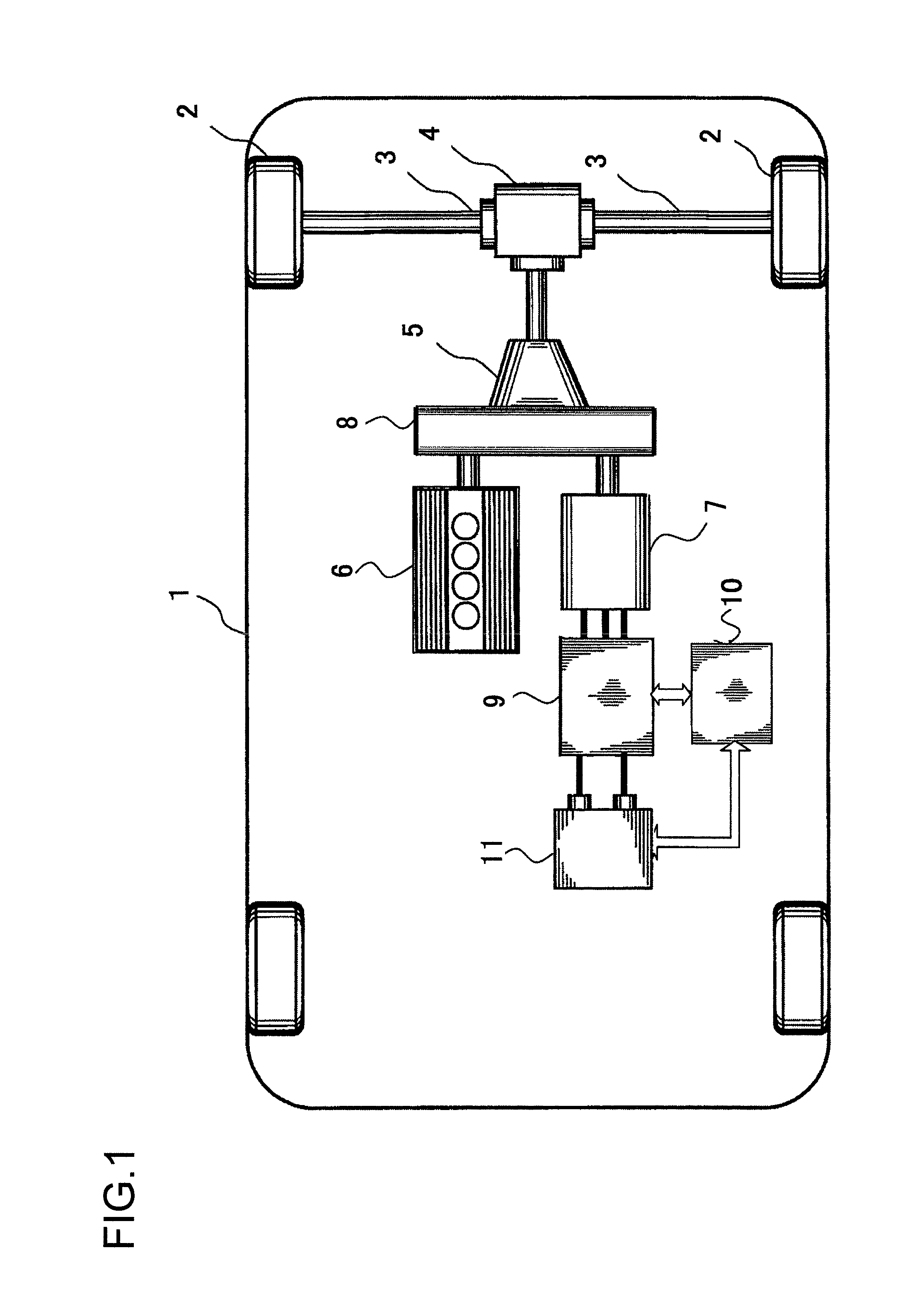
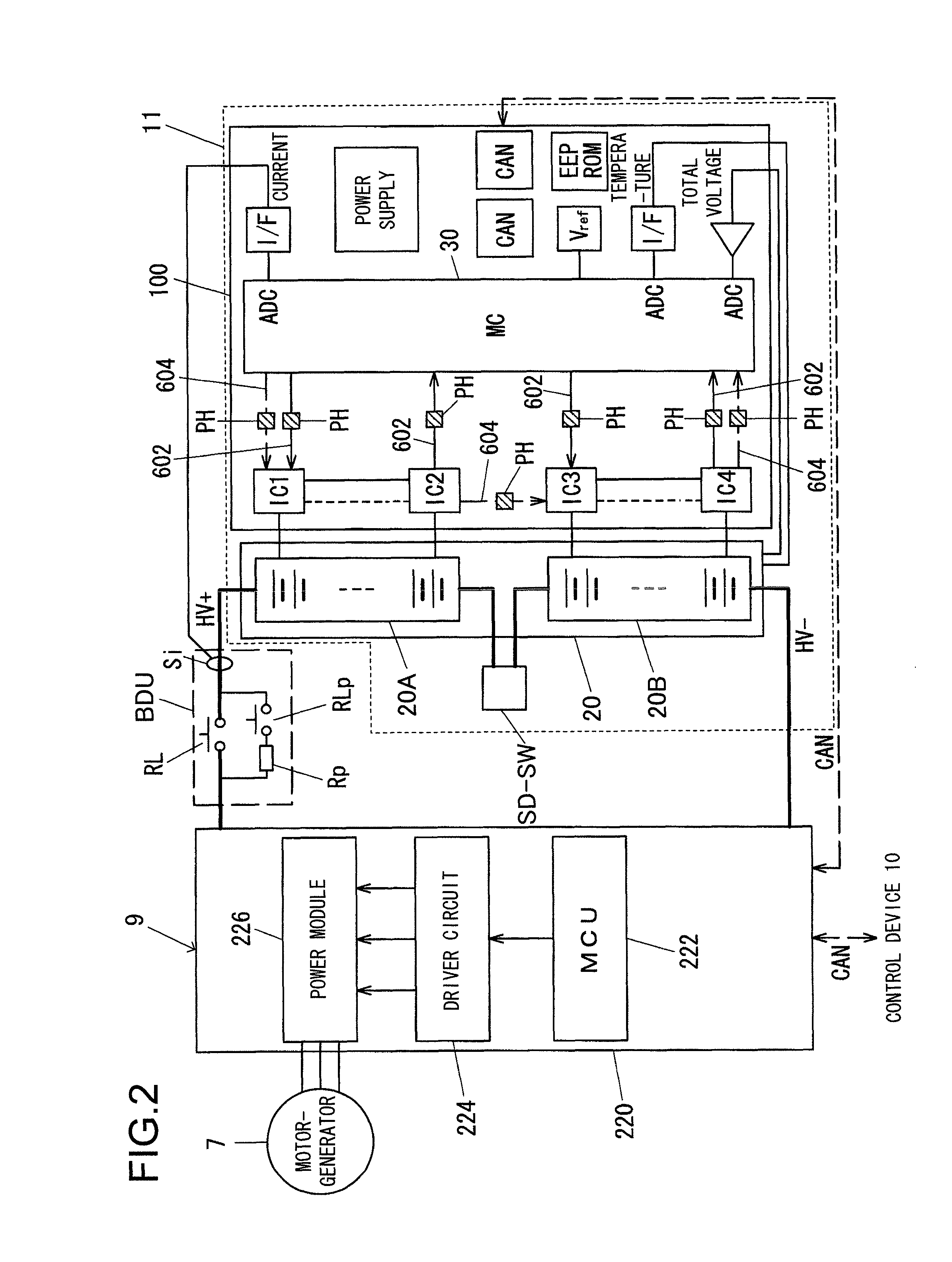
[0038]In the following, an embodiment for implementation of the present invention will be explained with reference to FIGS. 1 through 12. In the embodiment explained below, a case is explained in which the cell control device and the electricity storage device according to the present invention are applied to a drive system for a hybrid automobile. However, it should be understood that the structure of the embodiment explained below could also be applied to a railroad vehicle such as a hybrid train or the like. Moreover, the cell control device and the electricity storage device according to the present invention could also be applied to an electric automobile.

[0039]It should be understood that, in this specification, a group in which a plurality of unit secondary cells are connected in series will collectively be termed a “cell group”. Generally, a plurality of cell groups that are connected in series, in parallel, or in series-parallel are collectively termed a “battery module”, a...


PUM


Abstract

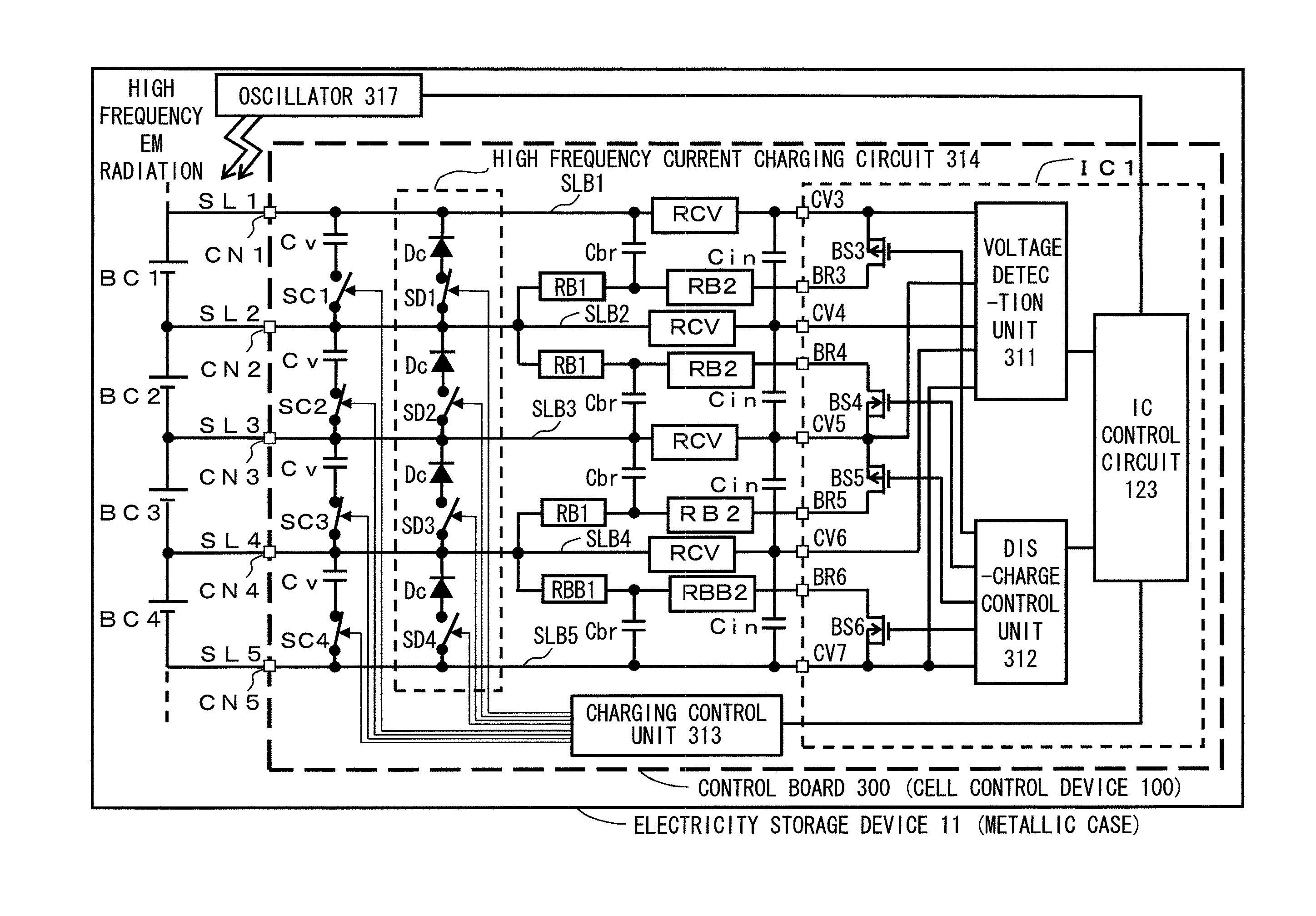
A cell control device according to the present invention includes: a discharge circuit that discharges each unit cell selected by the first switches among a plurality of unit cells connected in series; a charging circuit that charges each unit cell selected by the second switches among the unit cells connected in series, and; a voltage detection unit that detects a voltage of each unit cell via voltage detection lines respectively connected to positive and negative electrodes of the unit cells; an oscillator that irradiates high frequency electromagnetic radiation upon the voltage detection lines; and a charging control unit that controls switching of the first switches, thereby performing discharge of the each unit cell, and a charging control unit that controls switching of the second switches, thereby performing charging of the unit cells, based on voltages of the unit cells that are detected by the voltage detection unit.

Description

INCORPORATION BY REFERENCE[0001]The disclosure of the following priority application is hereby incorporated herein by reference: Japanese Patent Application No. 2010-285846, filed Dec. 22, 2010.BACKGROUND OF THE INVENTION[0002]1. Field of the Invention[0003]The present invention relates to a cell control device that controls the charging and discharging of cells in an electricity storage device, and to an electricity storage device that incorporates such a cell control device.[0004]2. Description of the Related Art[0005]In the prior art, a charging and discharging control system has been employed that controls a device for charging and discharging connected to the positive terminals and to the negative terminals of a cell group. Furthermore, with lithium ion batteries that have recently been implemented in practice, there is a possibility that a malfunction such as increase of the amount of heat generated or the like may take place if charging and discharging are not performed withi...

Claims


Application Information

Patent Timeline
Patent Type & Authority Patents(United States)
IPC IPC(8): H02J7/00H02J7/02B60L3/00B60L7/14B60L11/18B60L50/16
CPCB60L11/1866B60L7/14B60L11/14B60L11/1861B60L11/1868B60L3/0084B60L2200/26H02J7/0019Y02T10/7005Y02T10/92B60L2240/547Y02T10/7061Y02T10/7055B60L2210/10B60L2210/40B60L2220/14B60L2240/545B60L2240/549B60L2240/80B60L2270/20Y02T10/7077Y02T10/7044Y02T10/7241Y02T10/7066Y02T10/7216B60L50/16B60L58/14B60L58/15B60L58/20B60L58/22Y02T10/70Y02T10/7072Y02T10/72
Inventor MIURA, HIKARUKUDO, AKIHIKO
Owner HITACHI ASTEMO LTD
Learn More